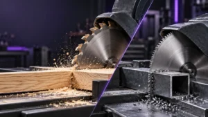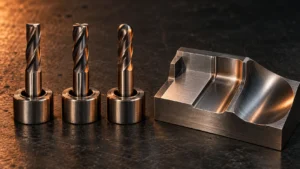
A fly cutter can produce a very uniform finish across a broad, flat surface—but only when the machine, tool body, cutting edge, workholding, and cutting strategy are suited to the job. It is not a universal replacement for a face mill. A single cutting edge concentrates force, so a fly cutter can expose spindle runout, excessive tool overhang, weak clamping, or poor balance faster than many multi-insert tools.
This guide explains how fly cutters work, the main structures available, when to choose a fly cutter instead of a face mill, and what to check before sourcing a standard or custom tool. It is written for CNC machining shops, fixture and mold manufacturers, distributors, and procurement teams that need a clear decision framework rather than a generic product list.
What Is a Fly Cutter?
A fly cutter is a rotary milling tool that uses one primary cutting edge, or in some designs two opposed cutting edges, to machine a flat surface. The cutting edge travels in a wide circular path as the spindle rotates. It is commonly used for light surfacing and finishing operations on fixture plates, machine components, mold bases, aluminum panels, and other parts where a broad, visually consistent surface matters.
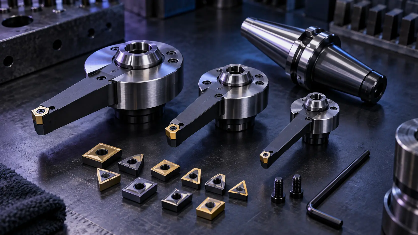
A typical fly cutter system includes a body or arbor, a cutting-edge seat or tool-bit pocket, fastening hardware, and a cutting element. The cutting element may be a ground HSS tool bit, a brazed tip, or a replaceable carbide insert. The usable sweep diameter is determined by the body and the radial position of the cutting edge; a larger sweep can cover a wider surface, but it also increases the importance of balance and rigidity.
The simple structure is one reason fly cutters remain useful. With one active edge, the surface is generated by one geometry at one height. However, that same single-edge design means the full cutting load is carried by one point during engagement. Good results depend on the complete machine-tool-workpiece system, not only on the cutter body.
How a Fly Cutter Creates a Surface
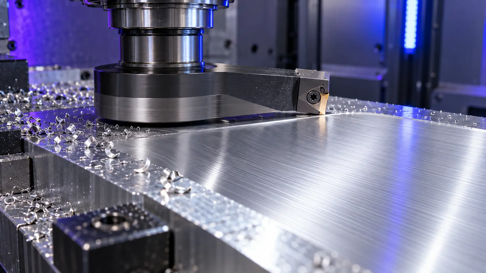
Each revolution of a fly cutter produces an arc-shaped tool mark. The visible pattern and surface finish depend on feed per revolution, cutting-edge radius, machine stability, runout, workpiece support, and edge condition. A sharp, correctly presented edge on a stable setup can leave a consistent finish because there is no second or third insert at a different axial height adding another pattern.
That benefit has practical limits. If the tool body is unbalanced, the cutting edge is extended too far, the holder runs out, or the workpiece moves under load, the single point can create chatter marks, stepped surfaces, or inconsistent finish. Treat fly cutting as a finishing process that must be set up deliberately—not as a high-removal shortcut.
Why Single-Edge Consistency Matters
A multi-insert face mill may have small height differences between inserts, insert seats, or assembly conditions. In many production operations this is acceptable and the productivity gain is worth it. A fly cutter avoids insert-to-insert height variation because one active edge forms the surface. This can be useful when a uniform cosmetic pattern or a controlled final pass is more important than removal rate.
What Influences Flatness and Finish
- Spindle and holder runout: Runout changes how the edge meets the workpiece and can affect finish consistency.
- Radial extension: A longer extension increases bending leverage and raises the risk of vibration.
- Tool-body balance: Balance becomes more important as sweep diameter and spindle speed increase.
- Workholding: A thin plate, poorly supported part, or interrupted surface can chatter even with a good cutter.
- Edge geometry and condition: Rake, clearance, nose condition, insert seat cleanliness, and wear must match the material and finishing target.
Types of Fly Cutters
HSS Tool-Bit Fly Cutters
Traditional fly cutters hold a ground HSS tool bit. They can be practical for development work, light-duty mills, and operations where the operator needs to adjust the cutting geometry. Their main advantage is flexibility: an experienced team can grind a geometry suited to a specific material or finish. Their limitation is consistency, because performance depends on repeatable grinding and correct setup.
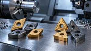
Indexable Fly Cutters
Indexable designs use replaceable carbide inserts in a defined seat. They can simplify edge replacement, inventory control, and repeat production. The insert geometry, clamping method, seat accuracy, and compatible screw must be specified together. If your application needs an insert-based system, review ZIROO TOOLS’ indexable cutting tools for related machining concepts and sourcing considerations.
Adjustable-Arm Fly Cutters
An adjustable arm can change the sweep radius for different workpiece widths. This flexibility can be valuable for prototype shops and low-volume fixture work. The trade-off is that every adjustment changes the balance and stiffness of the tool. The assembly must be inspected and set conservatively before machining.
Custom Fly Cutters
A custom fly cutter may be appropriate when a standard body cannot reach the required width, clearance, holder interface, insert geometry, or surface target. Custom work should begin with the finished part drawing and the machine setup—not only a desired cutter diameter. For project-based designs, ZIROO TOOLS can review drawings through its OEM/ODM custom tooling process.
Fly Cutter vs Face Mill: Which One Should You Choose?
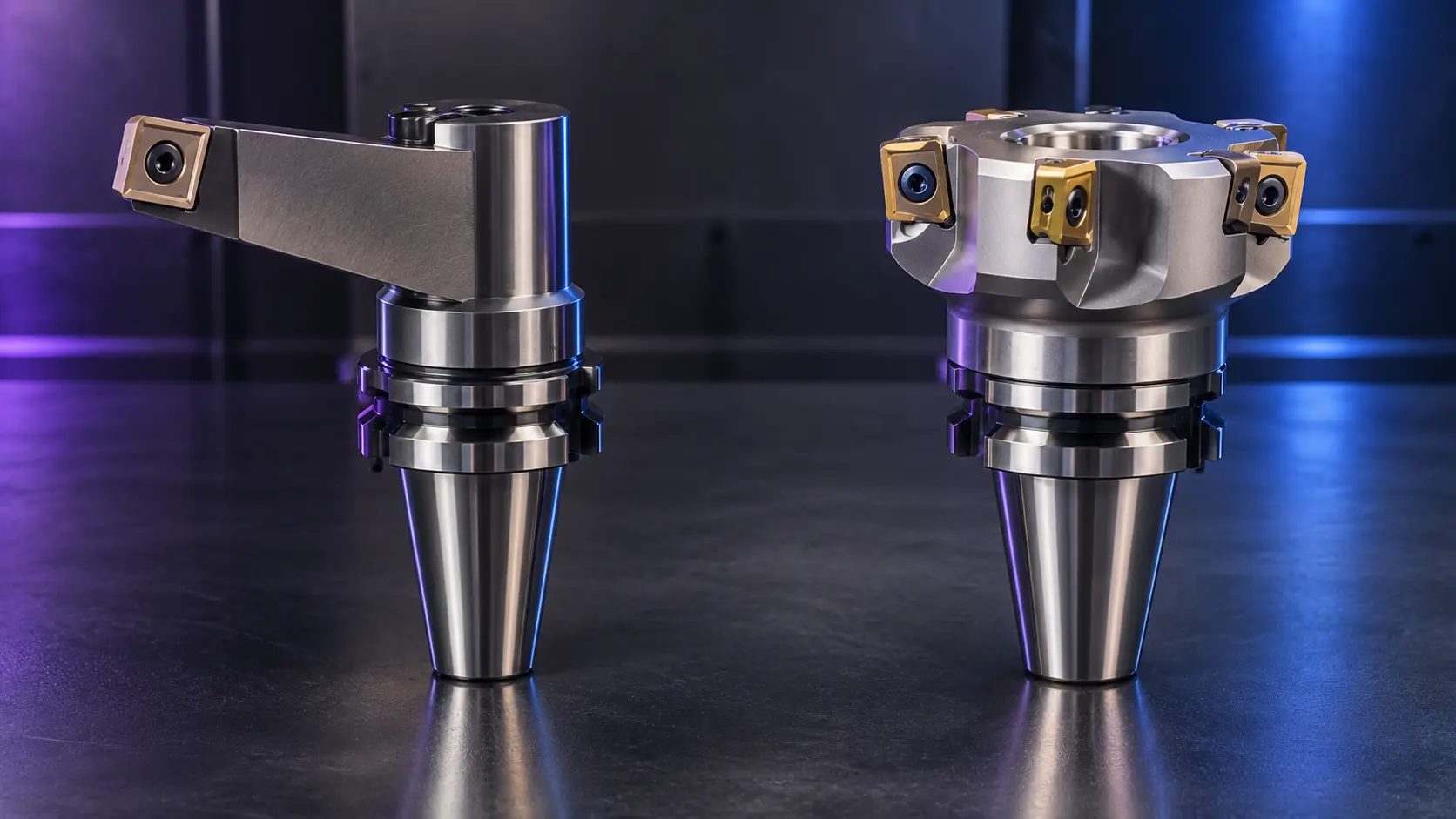
| Decision factor | Fly cutter | Face mill |
|---|---|---|
| Active cutting edges | Usually one primary edge | Multiple inserts or teeth |
| Best-fit operation | Light surfacing and controlled final finishing | General facing, roughing, and productive batch machining |
| Surface pattern | One consistent cutting-edge path when setup is stable | Depends on insert condition, seating, runout, and wiper geometry |
| Material removal rate | Usually lower | Usually higher |
| Sensitivity to rigidity | High, especially with long radial extension | Generally more tolerant, but still depends on cutter and setup |
| Best purchasing question | Can the machine and workholding support a stable finishing pass? | Do you need output, repeatability, and high removal rate? |
Choose a fly cutter when the part is already near final size and you need a controlled finish across a broad, continuous plane. Typical examples include aluminum fixture plates, mold bases, precision mounting faces, and cosmetic panels. Choose a face mill when the work requires heavier stock removal, faster cycle time, robust production output, or more tolerant behavior under demanding material conditions.
A face mill is not automatically inferior for finishing. With the correct insert geometry, seating, wiper strategy, machine condition, and toolpath, it can also produce a good surface. Likewise, a fly cutter is not automatically best for every flat part. The correct choice starts with the process requirement, then matches tool structure to the machine and part.
When a Fly Cutter Is the Right Choice
A fly cutter is worth considering when you have a broad, relatively continuous face and a final-pass requirement that favors visual consistency over high material removal. It can be useful for low- to medium-volume work, development fixtures, aluminum components, mold or jig reference faces, and parts that need a single controlled finishing process.
It is less suitable for deep roughing, strongly interrupted surfaces with many holes or pockets, weak workholding, high-output production where every second matters, or a machine with uncertain spindle condition. In those cases, a face mill, an end mill, another finishing process, or a redesigned operation may be more reliable. For broader milling geometry decisions, see ZIROO TOOLS’ end mill types for CNC machining guide.
How to Choose a Fly Cutter

1. Define the Actual Finishing Requirement
Start with the drawing requirement: flatness, surface texture, visual appearance, machined width, and whether the face is a sealing, locating, cosmetic, or functional surface. Specify the result you need, rather than instructing the supplier to use a particular tool before the process is reviewed.
2. Confirm Material and Surface Condition
Material behavior affects edge geometry, coating, coolant approach, chip formation, and cutting force. State the material grade, heat-treatment condition, stock form, scale or oxide condition, and whether the face contains holes, interrupted edges, or welds. A finishing strategy for aluminum does not automatically transfer to stainless steel, cast iron, or hardened tool steel.
3. Match Sweep Diameter to the Part and Machine
The cutter must cover the machining width with sufficient clearance, but the largest possible diameter is rarely the safest choice. Greater radius increases leverage and makes balance and stiffness more critical. Use the smallest practical sweep that meets the required coverage and access.
4. Evaluate the Holder, Projection, and Balance
Confirm the spindle interface, holder type, usable gauge length, available clearance, and maximum practical projection. Keep the cutting edge and radial arm as short as the application permits. Check that the body, arm, insert, screw, and counterweight arrangement remain secure and balanced after adjustment.
5. Select the Edge System
For a ground HSS system, define the required tool-bit section, geometry, and sharpening process. For an indexable design, define the insert family, material range, edge preparation, clamping method, screw, and replacement availability. Do not treat an insert code as sufficient by itself: the seat and cutter-body design also affect performance.
6. Plan a Controlled Sample Validation
Before moving to repeat production, validate the cutter on a representative material and machine whenever the application is sensitive to flatness or appearance. Keep the test plan focused. Record the tool assembly, holder, projection, workholding method, cutting-edge condition, machining path, and the inspection method used for the finished surface. This makes it possible to distinguish a cutter-design issue from a machine, holder, or process issue.
A sample should answer practical questions: Does the tool reach the full face without interference? Is the part adequately supported throughout the pass? Does the finish meet the drawing requirement after cleaning and inspection? Can the same setup be repeated by another operator? For repeat orders, retain the approved cutter drawing, insert or tool-bit specification, inspection points, and packaging requirement. This is more useful than approving a sample only by appearance.
7. Consider the Complete Tooling System
A fly cutter body, cutting edge, holder, pull stud or retention system, spindle, fixture, and machining program work as one system. A change in one component can affect the result. For example, a different holder can increase runout or projection; a different insert batch can change edge preparation; a revised fixture can allow a thin plate to move. When comparing quotations, ask what is included, what replacement parts are compatible, and which dimensions must remain controlled between batches.
Chatter and Surface-Finish Troubleshooting
| Observed issue | Likely causes | What to check first |
|---|---|---|
| Chatter marks or audible vibration | Excessive extension, poor balance, weak clamping, worn spindle, or aggressive engagement | Tool projection, holder condition, workholding, cutter balance, and pass strategy |
| Stepped or uneven surface | Runout, tram error, loose insert, contaminated seat, or unstable part | Spindle/holder runout, insert seat, fastening torque, and machine alignment |
| Tearing or poor cosmetic finish | Dull edge, unsuitable geometry, built-up edge, vibration, or inconsistent feed | Cutting edge, material condition, coolant/lubrication method, and setup rigidity |
| Premature edge damage | Interrupted cuts, overload, unsuitable insert grade, or loose clamping | Part interruptions, edge geometry, insert retention, and machining sequence |
When a finish problem appears, do not immediately increase cutting force or change several variables at once. Start with mechanical stability: inspect the holder, projection, tool-body assembly, insert seat, clamp condition, and part support. Then review the cutting edge and machining strategy. A stable process is easier to optimize than an unstable process with new parameter changes added on top.
Safe Setup and Operation Checks
Because a fly cutter sweeps a wide rotating path, its clearance must be checked with the machine stopped before a cutting cycle begins. Confirm that the tool clears clamps, fixtures, probing hardware, doors, and machine components through the entire programmed path. Verify that the cutting element and all fastening hardware are correctly seated, and remove chips or contamination from the insert seat before assembly.
Start a new setup cautiously and observe the first pass for vibration, unusual noise, chip control, and surface pattern. Stop and inspect the system when a change occurs rather than continuing with a damaged edge or loose assembly. Operators should follow the machine manufacturer’s instructions and applicable workshop safety procedures for guarding, PPE, and tool assembly.
When the part is a thin plate or a long fixture base, support must be considered across the entire machined area, not only at the visible clamp points. Material can relax after the cut or deflect between supports. Record the clamping sequence and any support blocks used during sample approval, then use the same method in production. This helps protect both the surface result and the dimensional outcome.
Repeatable setup discipline is essential for reliable finishing results.
B2B Buying and Custom Tooling Checklist
A useful fly cutter quotation requires more than an outside diameter. Send the following information when requesting a standard or custom solution:
- Part drawing or a clear sketch showing the machined face, width, access, and tolerance.
- Material grade, hardness or heat-treatment condition, and stock surface condition.
- Operation purpose: roughing, semi-finishing, final finishing, or cosmetic surfacing.
- Required flatness, surface requirement, and whether a visible machine pattern is acceptable.
- Machine model, spindle interface, speed range, holder type, and available clearance.
- Current tool specification and the issue you need to solve, such as chatter, uneven finish, short life, or poor productivity.
- Preferred edge system: HSS tool bit, brazed tip, or compatible indexable insert.
- Expected sample quantity, production quantity, inspection needs, branding, and packaging requirements.
These details allow a supplier to discuss cutter geometry, sweep range, holder interface, insert or tool-bit arrangement, inspection points, and repeat-order consistency before production. For machining projects in demanding sectors, your application information can also be reviewed against related aerospace tooling solutions requirements such as material, reach, rigidity, and finish control.
Common Purchasing Mistakes to Avoid
- Ordering only by diameter: Sweep diameter does not define holder compatibility, cutting-edge reach, balance, insert seat, or usable clearance.
- Requesting a “mirror finish” without a specification: State the drawing requirement, inspection method, material condition, and whether cosmetic appearance or functional flatness is the priority.
- Ignoring the whole setup: A cutter cannot correct poor spindle condition, weak clamping, excessive tool projection, or inadequate part support.
- Using a finishing fly cutter for roughing: This can raise cutting force, damage the edge, and cause chatter that is incorrectly blamed on the cutter body.
- Approving a sample without traceability: Record the approved geometry, edge system, assembly, and inspection conditions so the next order can be repeated consistently.
For distributors and private-label buyers, it is also important to agree on marking, packaging protection, spare insert or tool-bit availability, documentation, and the process for handling an application mismatch. These requirements should be defined before the production order, especially when a custom cutter must be reproduced months later.
Frequently Asked Questions
What is a fly cutter used for?
A fly cutter is mainly used to machine broad, flat surfaces with a controlled final finish. It is often considered for fixture plates, mold bases, mounting faces, aluminum components, and low- to medium-volume surfacing where consistent surface appearance matters.
What is the difference between a fly cutter and a face mill?
A fly cutter normally uses one primary cutting edge, while a face mill uses multiple inserts or teeth. Fly cutters are often chosen for controlled finishing; face mills are commonly selected for higher material removal and productive facing operations.
Can a fly cutter be used on aluminum?
Yes, it can be suitable for aluminum finishing when the edge geometry, machine stability, workholding, and cutting strategy are appropriate. The correct setup depends on the alloy, finished width, required appearance, and machine capability.
Why does a fly cutter chatter?
Common causes include excessive radial extension, imbalance, weak workholding, runout, a dull or poorly matched edge, and interrupted cutting. Check mechanical stability before changing several cutting variables at once.
Is a fly cutter good for heavy roughing?
Usually not. Fly cutters are commonly better suited to controlled surfacing and finishing. For heavy material removal or high-volume production, a face mill or another multi-edge milling solution is often more appropriate.
Should I choose an HSS or indexable fly cutter?
HSS tool-bit designs offer geometry flexibility and resharpening. Indexable designs can simplify repeatable edge changes and replacement management. Choose based on material, operator capability, production consistency, and the required finish.
What should I send for a custom fly cutter quotation?
Provide a drawing, material, machining width, surface requirement, machine and holder details, current tooling issue, preferred edge system, and expected quantity. This gives the supplier the information needed to assess a suitable design.
Can a fly cutter replace every face mill?
No. A fly cutter and face mill serve overlapping but different needs. A fly cutter may be useful for a broad final finishing pass; a face mill is often more suitable for higher removal rate, robust production, and demanding batch output.
Choose the Tool From the Process, Not the Label
A fly cutter can be an effective finishing tool when the part, machine, and setup support a stable single-edge pass. It becomes a poor choice when heavy removal, weak rigidity, highly interrupted cuts, or production speed are the dominant requirements. Define the result first, then select the cutter structure, edge system, holder, and machining strategy that can achieve it reliably.
Contact ZIROO TOOLS with your drawing, material, machining width, machine details, current tooling issue, and target quantity. Our team can review whether a standard or custom milling-tool approach is suitable for your application.