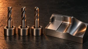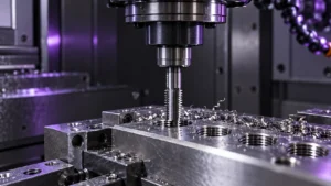
Chamfer milling is a CNC machining operation used to remove sharp edges, prepare components for assembly, create countersinks, and produce controlled transitions between surfaces. A reliable result depends on more than the nominal tool angle. Workpiece material, chamfer width, tool geometry, machine rigidity, toolpath strategy, and production volume all influence quality.
This guide helps CNC manufacturers, distributors, engineers, and purchasing teams select a suitable chamfer milling tool for production.
Why Chamfer Milling Matters
A sharp machined edge can cause handling injuries, interfere with assembly, chip during transport, concentrate stress, and reduce the consistency of coating or finishing. A controlled chamfer can improve part handling, guide mating components into position, reduce edge chipping, prepare surfaces for welding or coating, and improve finished appearance.
What Is Chamfer Milling?
Chamfer milling cuts a sloped surface along an edge. It can be applied to external edges, internal edges, hole entrances, hole exits, slots, pockets, complex profiles, and the back side of a component. A chamfer is normally specified by its angle and width, such as a 45-degree chamfer with a defined C dimension.
Chamfer, Bevel, Fillet, and Deburring
A chamfer is a flat angled surface. A bevel can describe a larger angled preparation area. A fillet is a curved transition with a radius and requires a radius tool rather than a chamfer mill. Deburring removes unwanted burrs; it may break an edge, but it does not automatically create an accurate specified chamfer.
Chamfer Mill vs. Countersink
A countersink is primarily designed to create a conical recess for a flat-head screw or similar fastener. A chamfer mill can also create an angled feature around a hole, but the tool must be selected according to the complete part requirement. Confirm the fastener drawing and required seat geometry before choosing the tool.
A chamfer is a flat angled surface. A bevel can describe a larger angled preparation area. A fillet is a curved transition with a radius and requires a radius tool rather than a chamfer mill. Deburring removes unwanted burrs; it may break an edge, but it does not automatically create an accurate specified chamfer.
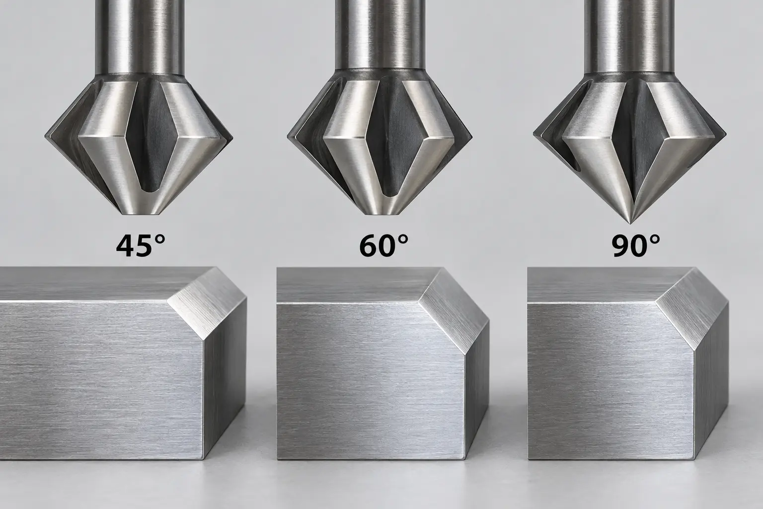
Chamfer Mill Angles and Applications
45-Degree Chamfer Mills
A 45-degree chamfer mill is a common general-purpose choice for edge breaking, assembly preparation, standard edge chamfers, small burr removal, and selected countersinking work.
60-Degree Chamfer Mills
A 60-degree tool is selected when the drawing or component geometry requires a steeper chamfer, special edge design, restricted clearance, or a non-standard assembly interface.
90-Degree Chamfer Mills
90-degree included-angle tools are commonly associated with countersinking, spotting, and screw-seat preparation. Confirm the tool’s intended operation before using it for a different edge feature.
Included Angle vs. Per-Side Angle
Before ordering a chamfer mill, confirm whether the supplier specifies the included angle or the per-side angle. The included angle is the total angle between two chamfer faces, while the per-side angle is measured from a reference face to one cutting edge. Always compare the drawing convention with the supplier specification.
Custom and Back-Chamfer Tools
Custom-angle tools may be required for aerospace, medical, mold, die, sealing, and complex assembly features. Back-chamfer tools machine the rear side of holes or edges where a conventional cutter cannot approach directly.
Common Chamfer Milling Tool Types
Solid Carbide Chamfer Mills
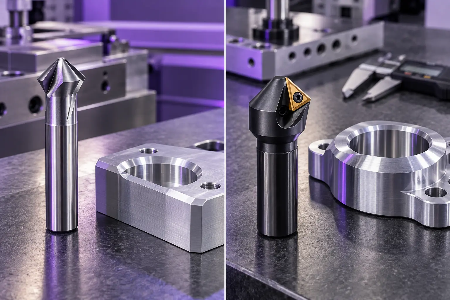
Solid carbide tools are often suitable for small and medium diameters, precision finishing, small-batch work, compact machining centers, and applications requiring a rigid cutting edge. If the edge is damaged, the complete tool may need replacement or regrinding. See our solid carbide end mills for related CNC tooling options.
Indexable Chamfer Mills
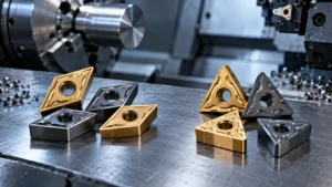
Indexable tools use replaceable inserts and are often suitable for larger diameters, repetitive production, higher material removal, and fast insert replacement. Insert seating and pocket cleanliness are essential for consistent runout and chamfer size. Compare related indexable cutting tools.
Back-Chamfer Tools
Selection should consider minimum hole diameter, maximum back-chamfer diameter, clearance, tool deployment, workholding, and CNC control capability.
How to Select a Chamfer Mill by Material
Aluminum and Non-Ferrous Metals
Aluminum can create long, sticky chips and built-up edge. Choose sharp geometry with effective chip evacuation and prevent chips from recutting inside the feature.
Steel and Alloy Steel
Balance edge strength and cutting efficiency according to hardness, finish, chamfer size, production quantity, machine rigidity, and coolant method.
Stainless Steel
Stainless steel can generate heat and work harden when the tool rubs. Maintain stable engagement, avoid dwell, control heat, and inspect runout before increasing cutting force.
Hardened Steel and Cast Iron
For hardened steel, confirm actual hardness, coating, edge preparation, interrupted-cut conditions, and machine stability with the supplier. Cast iron requires attention to abrasion, dust, chip control, and holder cleanliness.
Tool Geometry and Chamfer Width
Confirm cutting diameter, shank, flute or insert count, effective cutting length, edge preparation, coating, toolholder compatibility, feature clearance, and required C dimension. A larger chamfer may strengthen an edge but increase cutting load. A smaller chamfer can reduce force but is more sensitive to wear and runout.
Runout can cause uneven loading, variable chamfer width, poor finish, chatter, and premature wear. Check the holder, collet, spindle taper, insert seating, and tool cleanliness before changing parameters.
CNC Programming and Toolpath Strategy
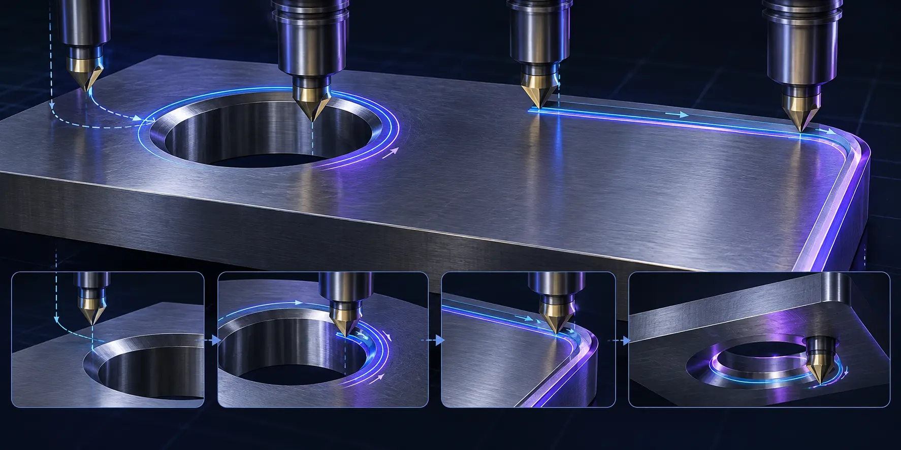
- Side milling: follow the component profile with controlled radial and vertical positioning.
- Plunge chamfering: use only when the tool is rated for the intended axial engagement.
- Circular interpolation: useful for consistent chamfers around holes and circular features.
- Back chamfering: plan entry, deployment, cutting, retraction, and safe clearance movements.
There is no universal speed or feed value. Start with the supplier’s recommended range and validate through a controlled test cut based on tool material, workpiece, diameter, engagement, machine rigidity, and coolant.
For mold cavities, cores, and complex edges, review our chamfering tools for mold machining.
Chamfer Milling Troubleshooting
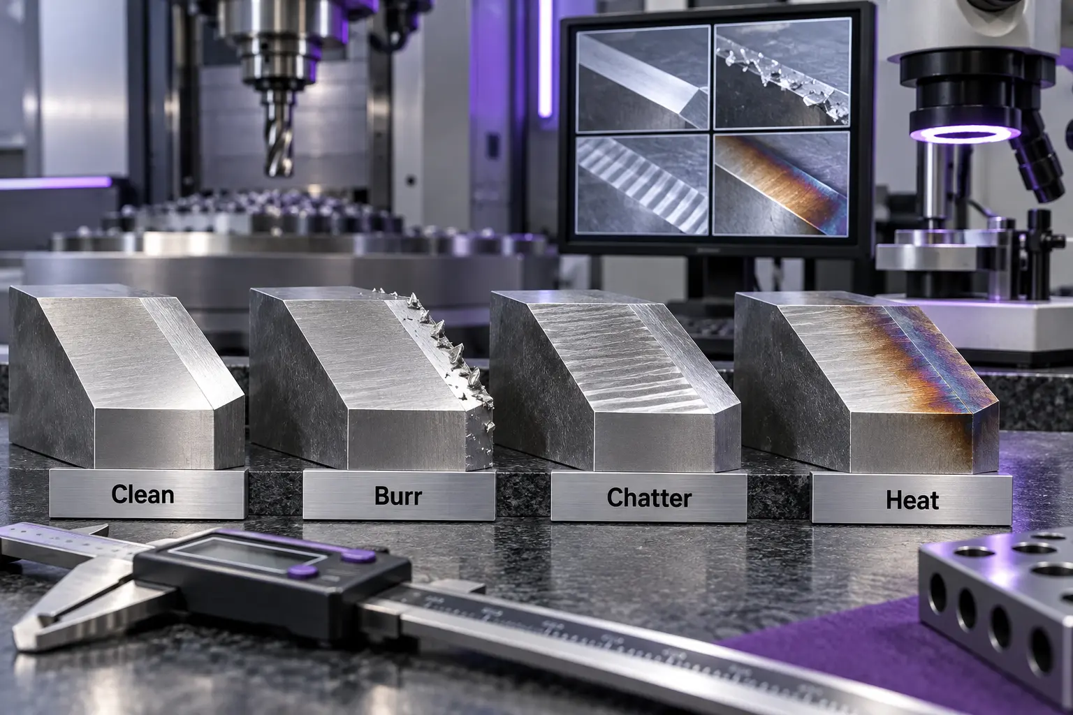
| Problem | Possible cause | Corrective direction |
|---|---|---|
| Burrs remain | Worn tool, unstable workholding, unsuitable path | Inspect the edge, verify the path, improve clamping |
| Chatter marks | Excessive overhang or weak setup | Reduce overhang and cutting load |
| Tool overheats | High load or poor chip evacuation | Review parameters, cooling, and chip removal |
| Chamfer width varies | Runout, offset, or insert seating | Measure runout and verify offsets |
| Edge chips | Impact loading or unsuitable grade | Stabilize the setup and match tool grade |
| Aluminum welds to tool | Built-up edge or chip recutting | Use suitable sharp geometry and evacuation |
Chamfer Mill Angle Selection Table
| Angle | Common applications | Selection points |
|---|---|---|
| 45° | General edge chamfering and assembly preparation | Check chamfer width and finish |
| 60° | Special edge profiles and V-shaped features | Confirm clearance and angle convention |
| 90° | Conical seats and countersinking-related features | Confirm included angle, hole diameter, and fastener requirements |
| Custom | Mold, aerospace, medical, and non-standard parts | Provide a drawing or CAD model |
Solid Carbide vs. Indexable Chamfer Mills
| Factor | Solid carbide | Indexable |
|---|---|---|
| Best fit | Small diameters, precision, varied jobs | Large features, repetitive production |
| Maintenance | Replace or regrind complete tool | Replace or index inserts |
| Changeover | Complete tool replacement | Insert replacement or indexing |
| Cost focus | Flexibility and precision | Repeatability and insert economy |
Compare total cost per accepted part, including tool changes, setup time, rejected parts, inventory, regrinding, and maintenance.
How Batch Size Changes Tool Selection
For prototypes and small batches, a standard solid carbide tool can provide flexibility. For medium batches, prioritize availability, repeatability, and setup time. For high-volume production, evaluate cost per accepted part, tool life, automatic measurement, insert availability, and supply consistency.
B2B Buyer Checklist
- Workpiece material and hardness
- Chamfer angle and C dimension
- External, internal, or back chamfer requirement
- Hole, slot, or edge dimensions
- Surface finish requirement
- Machine, spindle, holder, and coolant information
- Production quantity and target tool life
- Standard or custom tool preference
- Drawing, CAD file, or sample part
For special angles, lengths, shanks, or drawing-based solutions, see our custom CNC tooling service.
Safety Notice
- Confirm tool, holder, spindle, and machine compatibility.
- Inspect for cracks, chipped edges, deformation, or abnormal wear.
- Secure the workpiece and toolholder.
- Wear eye, face, and appropriate personal protective equipment.
- Never remove chips by hand; stop the machine and use an approved tool.
- Verify offsets and clearance before a new program.
- Use a controlled test cut after changing material, tool, or parameters.
- For back chamfering, confirm tool path and interference clearance.
Frequently Asked Questions
What is chamfer milling used for?
It creates controlled angled edges, removes sharp corners, prepares assembly surfaces, creates countersinks, and machines front or back edges.
What is the best chamfer mill angle?
There is no universal best angle. The drawing, feature geometry, assembly requirement, and clearance determine the correct choice.
Is a chamfer mill the same as a deburring tool?
No. A chamfer mill creates a defined angled surface, while deburring primarily removes unwanted burrs.
Should I use solid carbide or indexable?
Solid carbide is often suitable for smaller tools and precision work. Indexable designs can be practical for larger features and repetitive production.
Can a chamfer mill machine hardened steel?
Some tools can, but suitability depends on hardness, grade, coating, geometry, rigidity, and cutting conditions. Confirm with the supplier.
How do I control chamfer width?
Control it through tool angle, diameter, tool position, offsets, compensation, and toolpath, then verify by measurement.
Why does chamfer milling produce chatter?
Common causes include excessive overhang, weak workholding, runout, vibration, or excessive engagement.
Can ZIROO TOOLS supply custom chamfer mills?
ZIROO TOOLS can review standard and non-standard requirements. Provide material, angle, C dimension, feature size, machine information, and drawing or CAD data.
Conclusion
Reliable chamfer milling requires coordination between the drawing, tool geometry, machine setup, CNC program, and inspection method. The correct tool depends on material, width, access, production quantity, rigidity, and replacement strategy—not only the nominal angle.
ZIROO TOOLS supports B2B customers with solid carbide chamfer mills, indexable cutting tools, custom-angle solutions, back-chamfer tools, and other CNC cutting tools. Request a chamfer milling quote and send your material, angle, C dimension, machine information, quantity, and drawing.