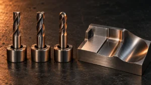
Bull Nose End Mill vs Ball Nose End Mill: How to Choose for CNC Milling
Choosing between a bull nose end mill and a ball nose end mill is a process decision, not a naming exercise. In a bull nose end mill vs ball nose end mill comparison, the right choice depends on the surfaces and edges in the part, the operation being planned, the CAM toolpath, the workpiece material, and the rigidity of the machine and toolholding setup. A bull nose end mill may suit a flat floor that blends into a controlled corner radius. A ball nose end mill may suit a continuously changing 3D contour. Either tool can be a poor choice when the contact point, reach, chip load, or finishing requirement is misunderstood.
This guide is written for manufacturers, distributors, process engineers, and B2B tooling buyers comparing a bull nose end mill vs ball nose end mill. It starts with cutter features, then moves to process planning, CAM verification, material selection, and supplier communication. Use it to create a technically clear shortlist; confirm the final geometry and cutting data against the toolmaker’s current specification and a controlled, representative trial.
Bull Nose End Mill vs Ball Nose End Mill: Quick Answer
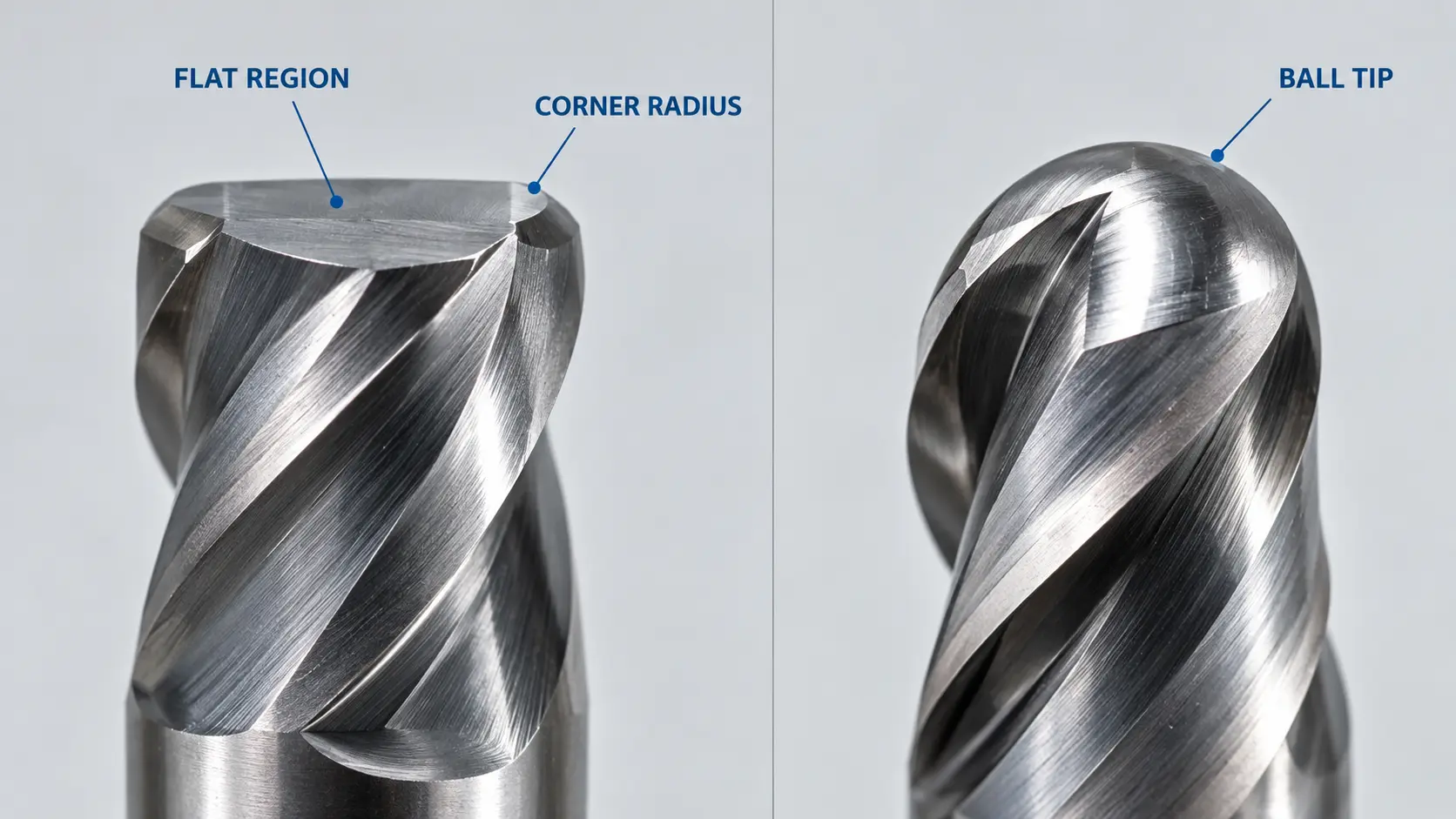
- Bull nose: a flat or near-flat cutting region with a defined corner radius, often considered for floors, walls, shoulders, and blended transitions.
- Ball nose: a spherical or hemispherical cutting end, often considered for sloped, contoured, and freeform 3D surfaces.
- Neither tool creates a sharp internal corner without a suitable secondary operation or a different cutter geometry.
- Final selection depends on the drawing, CAM path, workpiece, tool assembly, and machine rigidity—not on the tool name alone.
A bull nose end mill, also called a corner radius end mill in many catalogs, has a flat cutting end with a defined radius where the end meets the outside diameter. It can be considered when a process needs a relatively flat cutting area together with a softened, controlled transition at a shoulder, wall, or floor. The radius is a real geometric feature: it cannot produce an internal corner sharper than its own radius without another operation.
A ball nose end mill has a spherical or hemispherical cutting end. Its effective cutting diameter changes with the point of contact, so tool-center location, surface angle, tool axis, and programmed engagement have a direct influence on cutting conditions and surface pattern. Ball nose cutters are commonly evaluated for contoured, sloped, and freeform surfaces, especially where a continuously rounded end can follow a 3D path.
That summary is useful for screening, but it is not a universal rule. The radius-to-diameter relationship, flute and helix design, substrate, coating, holder, runout, CAM strategy, and workpiece all alter the result. Do not select a cutter from the shape name alone. Read the drawing, identify the actual contact, simulate the path, and verify the application with the manufacturer’s data.
Geometry First: How the Cutting Ends Engage the Workpiece
Bull Nose End Mill Geometry
Bull nose end mills generally combine a flat or near-flat cutting region with a defined corner radius. Depending on the design, the flat portion may support floor work while the radius blends into a vertical wall or outside profile. This geometry can be useful for pockets, shoulders, planar features, and blended transitions when the drawing calls for a defined radius rather than a sharp edge. Confirm the actual end geometry and center-cutting capability in the product drawing.
Engagement is not identical in every path. A floor cut may load the flat center, a wall pass may load the outside diameter, and a corner blend may load the radius itself. The engaged area changes again during profiling, entry, exit, or a path that moves across a slope. Available corner radii, flute counts, helix angles, edge preparations, and reliefs are product-specific, so the catalog drawing should be treated as part of the process definition.
The radius reduces the fragile sharp corner found on a square-end tool, but it also changes access. If the part requires a truly sharp internal corner, a bull nose cutter will leave material in that corner by design. The process may need a smaller-radius tool, a different cutter, EDM, broaching, or another secondary operation depending on the part specification.
Ball Nose End Mill Geometry
The cutting end of a ball nose end mill is a spherical surface. As the tool touches a flat, inclined, or curved feature, the local contact point moves over that sphere. The programmed tool-center position and the tool axis therefore matter as much as the nominal ball diameter. Near the ball tip, the effective cutting speed can approach zero, so tool-axis orientation and avoiding prolonged tip contact are important. A point near the tool tip does not behave like contact at the larger-diameter zone farther up the ball.
This changing effective diameter affects local cutting speed, chip formation, contact width, and the visible pattern left by adjacent passes. In some orientations, a portion of the ball may rub instead of cutting efficiently. In others, the ball can provide the continuous radius needed to follow a sculpted surface. The CAM system should account for the cutter shape, holder, tool axis, and machine kinematics; a visual path without a reliable gouge and collision check is not enough.
A ball nose cutter also leaves a rounded transition in an internal corner. It can follow a 3D form, but it does not create a sharp corner. If the design has a narrow slot, deep pocket, or near-vertical wall, verify access and contact rather than assuming that a smaller ball diameter automatically solves the problem. Reach, deflection, and holder clearance may become the limiting factors.
What the Geometry Changes in Practice
Geometry, flute design, tool orientation, and cutting conditions together affect contact area, local cutting speed, chip evacuation, rubbing risk, and the shape of cusps or scallops left between passes. A bull nose may offer a more predictable transition on a floor-and-wall feature when its radius matches the drawing. A ball nose may offer continuous contact on a changing contour when the tool axis and step-over are correctly controlled.
These are mechanisms to investigate, not guaranteed outcomes. A tool with an appropriate end shape can still chatter in a flexible setup, pack chips in the flutes, burn a workpiece, or leave unacceptable marks if the path and cutting data are unsuitable. Inspect the actual contact in CAM and review the finished feature against its drawing requirements.
Bull Nose vs Ball Nose End Mill: Technical Comparison Table
| Decision factor | Bull nose end mill | Ball nose end mill | What the buyer or process engineer should verify |
|---|---|---|---|
| End geometry | Flat end plus a defined corner radius | Spherical or hemispherical end | Drawing geometry, required radius, and available tool sizes |
| Typical engagement | Flat floors, shoulders, profiles, and blended corners may be feasible | Contoured, sloped, and 3D surfaces may be feasible | Actual contact in the programmed toolpath |
| Sharp internal corners | Radius leaves a controlled fillet; it cannot make a corner sharper than the tool radius | Ball geometry also leaves a radius or rounded transition | Corner specification and any secondary operation |
| Surface and cusp behavior | May be easier to control on floor-and-wall features and their transitions | Scallop height is strongly affected by contact point and step-over on 3D surfaces | CAM simulation and measured surface requirement |
| Roughing or finishing role | Can support roughing or finishing depending on design and process data | Often evaluated for contour finishing, but capability remains tool- and process-specific | Stock, radial and axial engagement, and manufacturer recommendations |
| CAM considerations | Profile, pocket, shoulder, rest, and applicable 3D paths | 3D contour, parallel, morph, flowline, or rest paths as applicable | CAM kernel, holder collision, gouge check, and tool axis |
| Step-over and scallop | Set from feature geometry and finish acceptance | Set from curvature, contact point, and scallop target | CAM scallop calculation and physical inspection |
| Material suitability | Depends on substrate, coating, edge preparation, geometry, and cutting data | Depends on the same factors; ball shape alone does not select a grade | Workpiece grade or hardness, coolant, and chip control |
| Machine and holder sensitivity | Rigidity and runout affect radius, floor, and shoulder quality | Rigidity, runout, axis motion, and tool-center contact are especially important on 3D work | Machine, holder, gauge length, runout, and vibration |
| Purchasing question | Can this radius and flute design meet the floor, wall, and edge requirement? | Can this ball diameter and path meet the contour and scallop requirement? | Drawing, CAD, machine limits, and trial criteria |
Use this table as a screening aid, not as a substitute for a product drawing or application review. Final selection should be confirmed against the supplier’s specification and a representative trial on the intended machine and material.
Choose by Operation: Match the Tool to the Milling Process
Floors, Walls, Shoulders, and Corner Blends
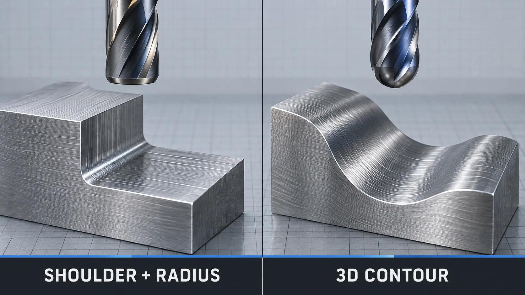
When a part combines a floor with a vertical wall or a specified blended edge, a bull nose end mill may be considered because its flat center and corner radius address two related features. The key question is whether the cutter radius matches the drawing and whether the selected diameter can reach the feature without holder interference.
Review floor flatness, wall finish, corner-radius tolerance, and the transition between passes. A path that appears correct in plan view can leave a mark where a floor pass meets a wall pass. Check the programmed lead-in, tool compensation, radial engagement, and any remaining stock. If the corner is tighter than the available radius, plan the follow-up operation before ordering the tool.
3D Contours, Sloped Surfaces, and Freeform Features
A ball nose end mill may be considered when the cutter must travel over a slope, blended surface, mold form, impeller-like feature, or other continuously changing contour. The rounded end can maintain contact through a changing path, but only if the tool axis and cutter location are appropriate for the surface.
Simulate the path with the actual ball diameter, holder, gauge length, and machine axes. Review near-vertical areas, tight concave regions, and transitions where the contact point approaches the tip. Define how scallop height, waviness, and blend quality will be inspected; “looks smooth” is not an acceptance criterion for a production drawing.
Roughing, Rest Machining, and Finishing Passes
Neither tool shape automatically defines its process role. Stock volume, material, machine power, tool diameter, flute design, axial and radial engagement, and required reach determine whether a candidate belongs in roughing, semi-finishing, rest machining, or finishing.
For roughing, evaluate chip evacuation, available power, rigidity, and the size of the remaining stock. For rest machining, inspect the material left by the previous tool and ensure that the smaller cutter can access it without excessive overhang. For finishing, prioritize contact control, path quality, tool condition, scallop acceptance, and dimensional inspection. Use the manufacturer’s cutting recommendations as the starting point and adjust only through a controlled prove-out.
When a Single Tool Does Not Complete the Process
A practical route may use a larger rougher or a different geometry for stock removal, then a bull nose or ball nose tool for semi-finishing and finishing. An inspection step or secondary operation may follow when the drawing requires a feature that one cutter cannot physically create. This process chain is an option, not a claim that multiple tools are always necessary.
Document the stock allowance between operations. Too much remaining material can overload the finishing tool; too little can make the tool rub against a distorted or work-hardened surface. The best sequence is the one that produces a stable, inspectable process on the intended equipment.
CAM Programming: Step-Over, Scallop Height, and Toolpath Checks
Step-Over Is a Surface-Requirement Variable
Step-over should be derived from the allowed surface cusp or scallop, tool geometry, local curvature, tool axis, material, stock, and the machine’s ability to hold the path. Do not copy a universal percentage from a generic chart and assume that it applies to every ball nose end mill or every surface.
With a ball nose cutter, the same nominal step-over can produce different contact and scallop behavior as the surface slope changes. The contact point may move toward the tip, toward a larger effective diameter, or across a region with a different tool-axis orientation. A bull nose path also needs review where the flat end, corner radius, and outside diameter share the work.
Scallop Height and Verification Workflow
Begin with the permitted scallop or finish requirement on the drawing or customer specification. In CAM, enter the actual ball or corner-radius geometry and calculate the predicted path for the local surface. Treat tool diameter, radius, surface angle, step-over, tolerance, and possible tool deflection as process inputs—not hidden assumptions.
Then cut a representative feature and measure it using the inspection method appropriate to the part. Compare the measured cusp, waviness, dimensional result, and visual pattern with the acceptance criteria. If the result is not acceptable, investigate contact location, tool condition, runout, vibration, path smoothing, and stock before simply reducing step-over. A smaller step-over can change cycle time without resolving a geometry or setup problem.
Collision, Gouge, and Holder-Clearance Checks
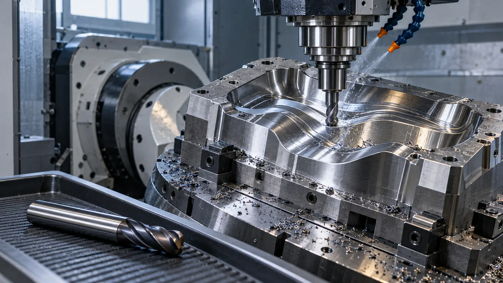
Include the complete tool assembly in simulation: cutter, neck, shank, holder, gauge length, and any extension. Check for holder collision, cutter gouge, machine-axis limits, retracts, lead-in and lead-out moves, rest material, and near-vertical contact. Review tool-axis smoothing and singularities on five-axis paths where applicable.
Follow the shop’s dry-run and controlled prove-out procedure before releasing a new path. A collision-free simulation is valuable, but it does not replace verification of workholding, coordinate systems, fixturing, and real machine behavior.
Material and Tool Construction: What to Compare Beyond the Shape
When comparing a carbide ball nose end mill with a bull nose end mill, compare the complete tool construction, not only the end profile. Substrate, coating, flute count, helix, chip space, edge preparation, relief, and coolant or air strategy must be considered with the workpiece and operation.
For aluminum and other non-ferrous materials, review chip space, edge sharpness, built-up-edge risk, and the coolant or air approach. For carbon and alloy steels, confirm that the coating, substrate, engagement, and cutting data match the grade and hardness. Stainless steels can demand careful heat and chip control because rubbing or poor evacuation may aggravate work hardening. Titanium and other difficult-to-machine alloys require a validated combination of engagement, rigidity, coolant delivery, and tool construction. Hardened or abrasive materials may require a different grade, edge preparation, or process sequence. These are selection prompts, not universal prescriptions.
Watch the process for clues: burrs, built-up edge, heat tint, chip packing, edge chipping, unusual sound, or rapid dimensional change can indicate a mismatch in geometry, data, coolant, or setup. A coating cannot compensate for poor workholding, and a premium substrate cannot correct a collision or excessive tool deflection. Use the selected tool’s technical recommendations and record the conditions under which the result was obtained.
Machine Rigidity, Toolholding, and Runout Checks
A capable end mill can underperform on a flexible machine or poorly supported part. Before comparing bull nose and ball nose geometry, confirm the complete cutting system:
- Spindle condition, holder cleanliness, and the seating of the tool
- Gauge length, overhang, extension, and available spindle power
- Measured runout at the relevant tool location
- Workholding, part support, thin-wall behavior, and fixture stiffness
- Axis backlash, accuracy, interpolation quality, and available machine travel
- Coolant delivery, chip evacuation, and access to the cutting zone
- Vibration or chatter, including changes during direction reversals
Long-reach tooling deserves special caution. Increasing reach can increase deflection and amplify the effect of runout or interrupted engagement. On 3D work, a ball nose path may also expose axis motion and tool-center contact errors that are less obvious on a simple planar cut. Shorten the assembly where the part allows it, support the workpiece, and validate the actual tool assembly in the machine.
A Practical Selection Workflow for B2B Buyers
- Start with the drawing or CAD model. Mark floors, walls, shoulders, internal corner radii, slopes, freeform surfaces, dimensional tolerances, and finish acceptance.
- Identify the operation and stock. Decide whether the candidate is for roughing, rest machining, semi-finishing, finishing, or one stage in a combined route.
- Select geometry and a diameter or radius range. Check access, reach, neck clearance, holder clearance, and the radius required by the part.
- Match construction to the material. Consider substrate, coating, flute count, helix, edge preparation, coolant, and the material’s grade or hardness.
- Confirm the CAM path. Check tool axis, contact location, step-over, scallop target, stock allowance, tolerance, holder clearance, and gouge prevention.
- Check the machine and setup. Verify rigidity, runout, workholding, gauge length, spindle capacity, coolant access, and prove-out controls.
- Run a representative trial. Record tool condition, process stability, cycle information, dimensional results, measured surface quality, and the accepted-part criteria.
This workflow also helps purchasing teams avoid an incomplete comparison. A lower unit price or familiar tool name is not enough if the diameter, corner radius, reach, coating, or inspection requirement does not match the application.
What to Include in an RFQ for Bull Nose or Ball Nose End Mills
A detailed RFQ lets a tooling supplier review the application instead of guessing from a part name. Include:
- Tool type and intended geometry: bull nose, ball nose, or an open comparison
- Diameter, corner radius or ball diameter, overall length, reach, neck, and gauge dimensions
- Flute count, helix, coating, and substrate if already specified
- Workpiece material, grade, hardness, condition, and any heat treatment
- Operation, stock condition, axial and radial engagement, and the current path strategy
- Machine, spindle, holder, gauge length, coolant, and workholding details
- Current cutting data, if available, plus observed chatter, burrs, heat, chipping, or tool damage
- Dimensional tolerance, surface or scallop acceptance, and inspection method
- CAD model or drawing, expected quantity, repeat demand, packaging, and inspection documentation
For an initial product review, explore ZIROO TOOLS CNC end mills. For custom dimensions, coatings, or drawing-based development, review the ZIROO TOOLS OEM/ODM process. Send the application information with the RFQ so the proposed geometry can be evaluated against the actual feature and process.
Safety Notice and Process Validation
Operators must follow the machine builder’s, toolholder manufacturer’s, cutting-tool supplier’s, coolant supplier’s, and workplace safety instructions. Use guarding and required personal protective equipment, secure the workpiece, inspect the cutter and holder, and verify programmed clearances before cutting. Confirm speeds, feeds, engagement limits, and coolant recommendations against the toolmaker’s current technical data.
This article cannot replace a tool datasheet, machine-builder instructions, workplace risk assessment, or controlled prove-out. Stop and reassess when there is chatter, unusual heat, chip packing, tool damage, unexpected dimensional change, or an abnormal surface pattern. Quarantine questionable parts until the cause and acceptance status are understood. Release the process only after a representative trial and inspection support the production requirement.
Frequently Asked Questions
Is a bull nose end mill the same as a corner radius end mill?
Usually, both terms refer to a flat-end mill with a defined corner radius. Catalog nomenclature can vary, so confirm the supplier’s drawing, radius definition, and end geometry before ordering.
Is a ball nose end mill only for 3D machining?
No. Ball nose cutters are commonly evaluated for contoured work, but suitability depends on feature geometry, access, CAM path, tool axis, material, and finish requirements. Confirm the contact and process result rather than assigning the tool a universal role.
Which gives a better surface finish: bull nose or ball nose?
Neither is universally better. Finish depends on the part geometry, toolpath, step-over and scallop, material, runout, machine rigidity, tool condition, and inspection method. Compare both against the same representative feature and acceptance criteria.
How do I choose step-over for a ball nose end mill?
Start with the allowed scallop or finish requirement and the CAM calculation for the actual ball diameter, surface angle, and tool axis. Then validate the result with a representative cut and measurement. Do not treat a generic step-over percentage as a guarantee for a changing 3D surface.
Can I use either tool on aluminum, steel, or stainless steel?
Possibly, but the substrate, coating, flute design, edge preparation, cutting data, coolant, and setup must match the material and operation. Use the selected tool’s technical recommendations and validate the process on the intended machine.
What information should I send a tooling supplier?
Send the RFQ checklist above: drawing or CAD, material and hardness, machine and holder, operation and stock, geometry requested, finish and tolerance criteria, quantity, and the current process problem. Photos or inspection results can also help explain chatter, chipping, burrs, or surface marks.
When should I request a custom bull nose or ball nose end mill?
Request a custom review when the required diameter, corner or ball radius, reach, neck clearance, coating, flute design, or holder interface is not available in the standard catalog. Include the drawing, material, machine setup, operation, and acceptance criteria so the proposed design can be evaluated before production.
What tool drawing and cutting data can ZIROO provide for RFQ review?
Ask the supplier to confirm the applicable tool drawing, dimensional fields, substrate or coating information, recommended cutting data, inspection requirements, and any sample-validation plan that applies to the quoted configuration. The exact documents depend on the tool and application.
Request a Geometry and Process Review from ZIROO TOOLS
A defensible answer to “bull nose end mill vs ball nose end mill” depends on the part, path, machine, and inspection plan. Share the feature geometry, workpiece, tool assembly, and acceptance criteria so the cutter size, corner or ball radius, construction, and application data can be reviewed together. A representative validation cut remains the final check for production use.
Contact ZIROO TOOLS for an application-based quotation and include the drawing or CAD model with your process details. The goal is a verifiable tooling decision—one that can be simulated, tested, measured, and repeated within your own CNC milling process.