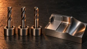
A carbide end mill should not be selected by diameter alone. Two tools with the same diameter can behave very differently because of their flute count, cutting-edge shape, helix, coating, cutting length, and intended workpiece material. The correct choice also changes between slotting, side milling, roughing, finishing, and three-dimensional profiling.
Start with the workpiece material and the operation. Then select the end profile, flute count, geometry, coating, and dimensions. Finally, confirm that the machine, holder, coolant method, and programmed toolpath can support the tool. This sequence prevents a common purchasing mistake: ordering a tool that looks correct in a catalog but does not have enough chip space, rigidity, reach, or edge strength for the actual cut.
This guide explains the main decisions for machinists, manufacturing engineers, distributors, and purchasing teams. It provides a practical starting method rather than universal cutting parameters. The tool supplier's application data and a controlled first-part trial should govern the final production setup.
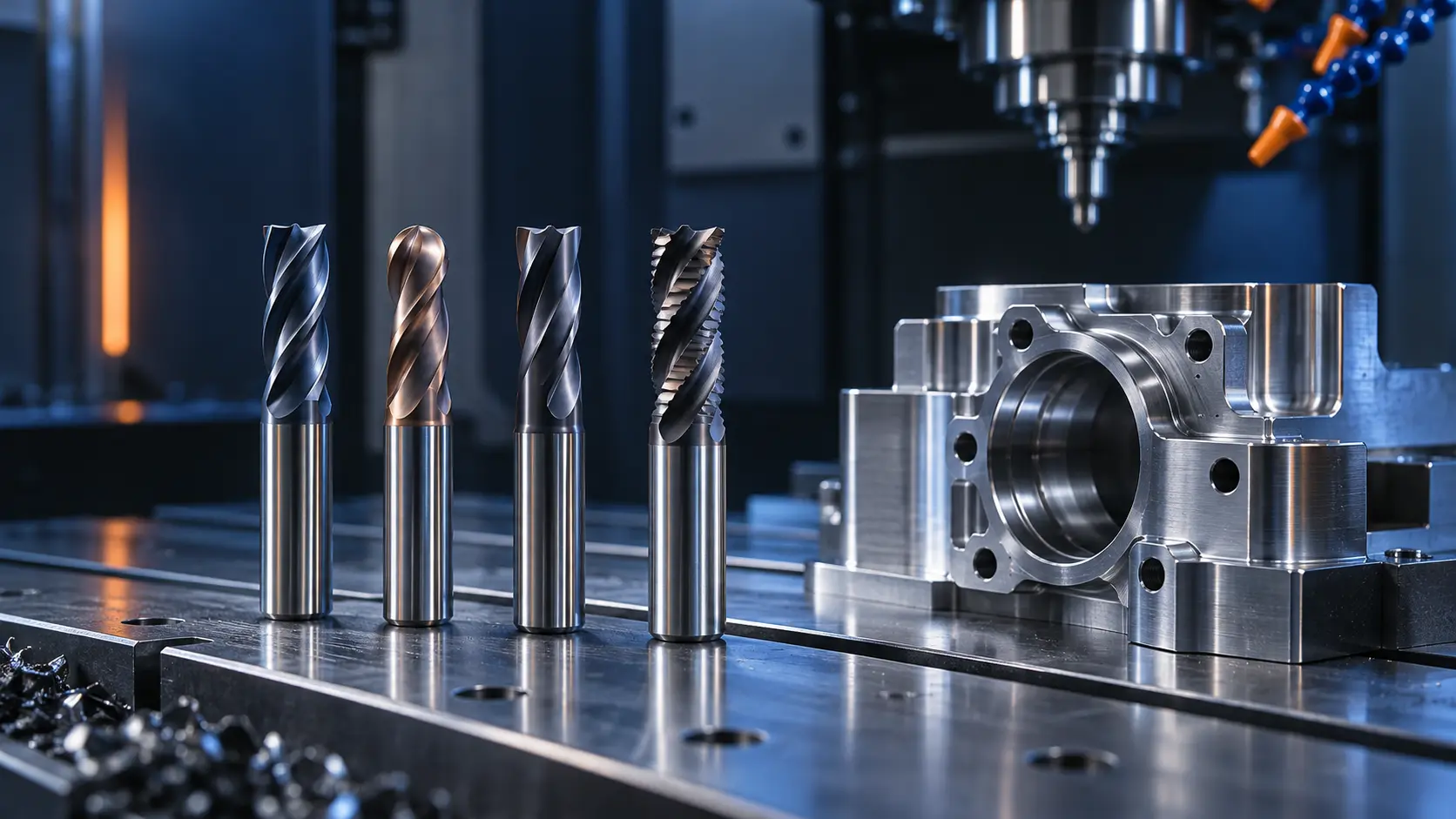
Quick Answer: Match the End Mill to the Material and Operation
The fastest reliable selection method is to answer four questions in order:
- What material will be cut? Aluminum, stainless steel, hardened steel, titanium, and graphite create different heat, wear, adhesion, and chip-control problems.
- What operation will the tool perform? Full-width slotting needs more chip space than light side milling. Roughing and finishing also favor different edge and flute designs.
- What shape must the tool create? Choose a square, ball nose, corner radius, or specialized profile according to the floor, wall, radius, and surface requirement.
- Can the setup support the tool? Check spindle speed, machine rigidity, holder condition, runout, coolant delivery, reach, and available toolpath strategy.
| Application Question | Primary Tool Feature to Review | Risk if Ignored |
|---|---|---|
| Workpiece material | Carbide grade, edge geometry, coating, flute space | Rapid wear, built-up edge, or chipping |
| Slotting or side milling | Flute count and chip evacuation | Chip recutting and excessive heat |
| Roughing or finishing | Edge form, profile, and rigidity | Low productivity or poor surface finish |
| Depth and reach | Cutting length, neck, overall length, and overhang | Chatter, deflection, or breakage |
| Machine and holder | Balance, runout, grip, and spindle capability | Inconsistent life and dimensional error |
A general-purpose end mill may be suitable for mixed, low-volume work. In a repeat production process, a material- and operation-specific tool can provide a more stable starting point. The right answer depends on the complete cutting system, not one feature printed on the box.
What Is a Carbide End Mill?
An end mill is a rotating cutting tool used on CNC mills and machining centers to remove material with its peripheral and, when designed for it, end cutting edges. It can machine slots, shoulders, pockets, contours, profiles, and complex surfaces. Unlike a conventional twist drill, an end mill is generally designed to cut laterally as well as axially, although its ability to plunge depends on the center-cutting geometry.
A solid carbide end mill is ground from a carbide blank rather than built around a high-speed-steel cutting body. Carbide provides high stiffness, wear resistance, and useful performance at elevated cutting temperatures. Those advantages also come with limitations: carbide is less tolerant of impact, excessive runout, unstable workholding, and interrupted loading than a tougher tool material might be.
For this reason, a carbide tool should be treated as part of a system. A premium end mill in a worn collet or flexible setup can fail before a more modest tool in a stable process.
Carbide vs. HSS End Mills
| Selection Factor | Solid Carbide | High-Speed Steel |
|---|---|---|
| Stiffness | Higher; useful for dimensional control and stable high-performance cutting | Lower; may deflect more under the same load |
| Wear and heat resistance | Generally supports higher cutting speed and longer wear life in a suitable setup | Typically requires more conservative cutting conditions |
| Toughness | More sensitive to shock, runout, and instability | Often more tolerant of impact and less rigid machines |
| Tool cost | Usually higher initial cost | Often lower initial cost |
| Best fit | Rigid CNC production, abrasive materials, precision and productivity | Manual machines, less rigid setups, special shapes, and some low-volume work |
Carbide is not automatically the best economic choice for every job. If the machine has significant spindle runout, the workpiece is poorly supported, or the operation repeatedly shocks the cutting edge, a carbide end mill may chip before its wear resistance produces a benefit. Conversely, a rigid CNC process may justify carbide through improved consistency, speed potential, and tool life.
Compare cost per completed part rather than tool price alone. Include cycle time, tool changes, scrap risk, surface-finish requirements, and the value of process stability.
Choose the Correct End Mill Profile
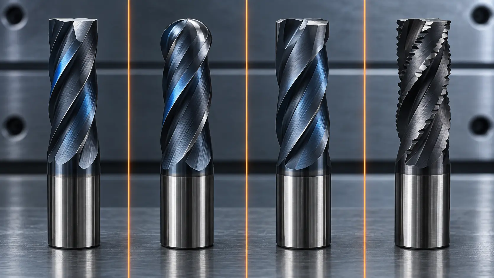
Square End Mill
A square end mill creates a nominally flat floor and a sharp internal corner based on the tool's corner condition. It is commonly used for shoulders, slots, pockets, and general side milling. The sharp corner provides versatile geometry but concentrates stress at the cutting edge. Chipping often begins there when the setup is unstable or the programmed engagement is too aggressive.
Ball Nose End Mill
A ball nose end mill has a rounded end for three-dimensional contours, molds, dies, and curved surfaces. Its effective cutting diameter changes across the ball. Near the center, cutting speed approaches zero, so toolpath, tilt, stepover, and surface-speed control become important. It is not normally the first choice for producing a broad, flat floor.
Corner Radius End Mill
A corner radius end mill adds a controlled radius between the end and peripheral cutting edges. The radius can strengthen the corner and reduce the stress concentration found on a sharp square edge. It is useful when the part drawing permits a corner radius and the process needs better edge strength without the fully rounded profile of a ball nose tool.
Roughing End Mill
A roughing end mill uses a serrated or chip-splitting edge form to divide chips and manage cutting load during material removal. It can be useful for heavy roughing, but it normally leaves a surface that requires a finishing pass. Confirm the intended material, stock allowance, machine power, and finishing plan before selecting this profile.
How Many Flutes Should a Carbide End Mill Have?
Flute count changes two competing characteristics. More flutes provide more cutting edges and a stronger core, but they reduce the space available for chips. Fewer flutes provide larger chip gullets, but fewer edges pass through the cut during each revolution. The best choice depends on material, radial engagement, axial depth, tool diameter, and chip-evacuation method.
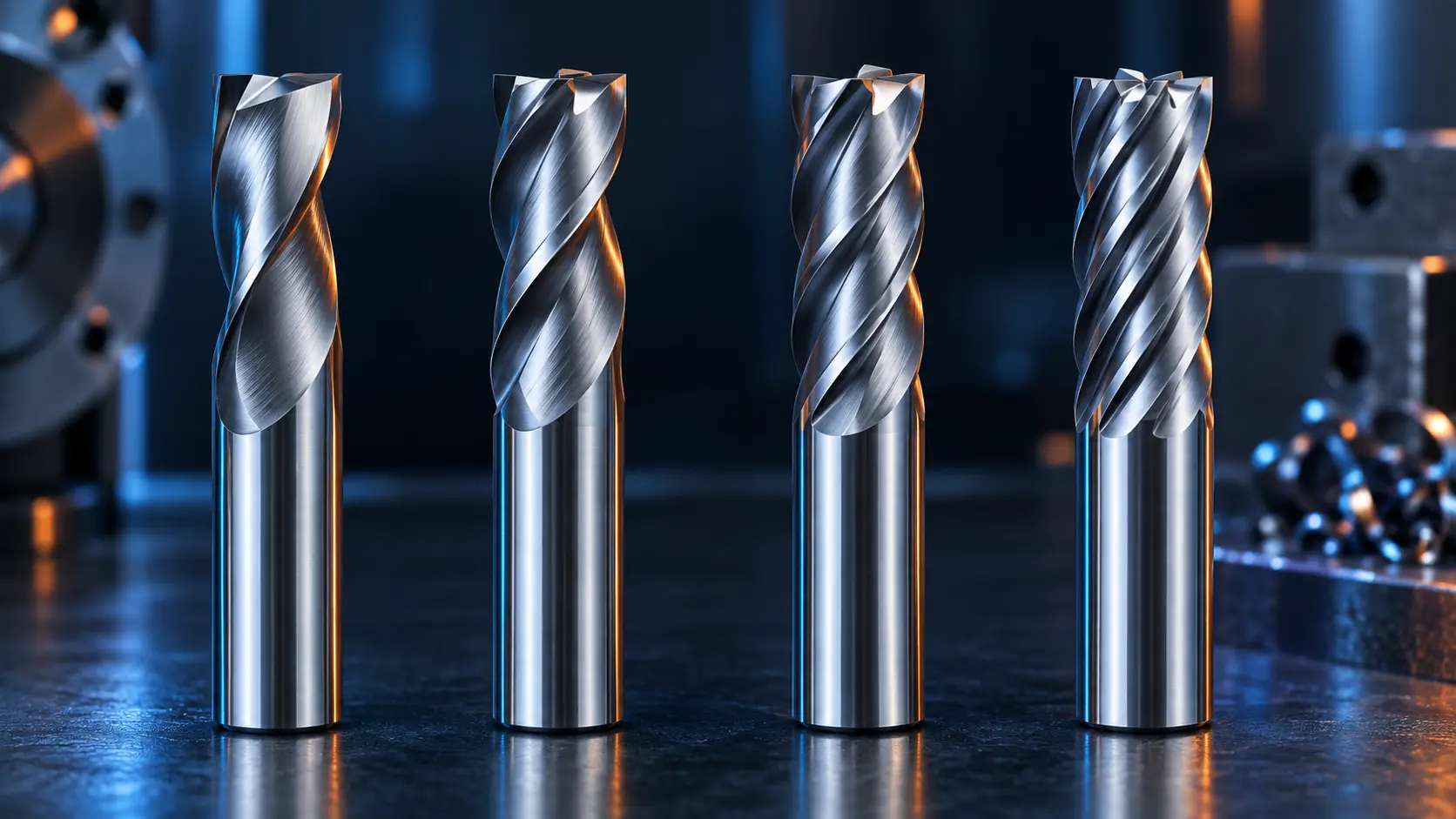
Two-Flute End Mills
Two-flute tools provide generous chip space and are often considered for full slots, soft or gummy materials, and applications where evacuation is difficult. They are widely associated with aluminum machining, but flute count alone does not make a tool suitable for aluminum. Edge sharpness, helix, flute finish, coating, and toolpath also matter.
Three-Flute End Mills
A three-flute design can balance chip space with an additional cutting edge. It is frequently considered for productive aluminum milling and for operations that need more feed capability than a comparable two-flute tool while retaining useful evacuation space. Validate performance in full slots separately from lighter radial cuts.
Four-Flute End Mills
Four-flute tools are common in steel and general-purpose milling. Their larger core and additional edges can support stable side milling and finishing. In a deep, full-width slot, however, the smaller flute space can trap chips if coolant, air blast, flute geometry, or toolpath does not remove them effectively.
Five or More Flutes
Multi-flute tools can increase the number of tooth engagements per revolution and are often useful in high-efficiency side milling, finishing, or harder materials with controlled radial engagement. They are not simply “faster” versions of four-flute tools. Feed per tooth, spindle capability, chip thickness, radial engagement, and evacuation must all support the additional flutes.
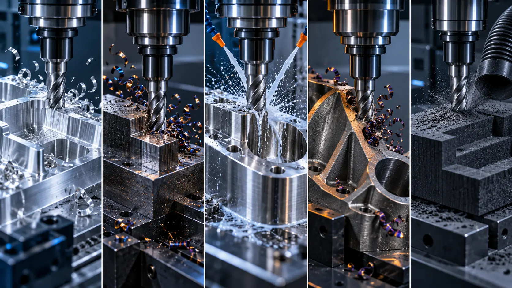
Select a Carbide End Mill by Workpiece Material
| Workpiece Material | Primary Cutting Challenge | Tool Features to Evaluate |
|---|---|---|
| Aluminum | Material adhesion, built-up edge, and chip volume | Sharp edge, polished or open flutes, suitable coating or uncoated geometry, large chip space |
| Mild and alloy steel | Wear, heat, and changing engagement | Edge strength, carbide grade, coating, and general-purpose or material-specific geometry |
| Stainless steel | Work hardening, heat concentration, and adhesion | Positive cutting action, consistent chip load, coating, coolant, and stable engagement |
| Hardened steel | Abrasive wear, high cutting forces, and edge failure | Rigid tool and setup, suitable grade and coating, short overhang, finishing allowance |
| Titanium alloys | Heat near the cutting edge and limited thermal conductivity | Heat-resistant system, controlled engagement, edge strength, coolant delivery, and toolpath |
| Graphite | Abrasive wear and dust | Wear-resistant tool system, suitable coating, dust management, and machine protection |
For aluminum, prioritize chip evacuation and resistance to material pickup. A sharp edge and smooth flute surface can be as important as the number of flutes. Do not assume that every dark-colored coating is appropriate; some coating and workpiece combinations increase adhesion.
When machining stainless steel, avoid dwelling and uncontrolled rubbing that may work-harden the surface. Maintain a stable chip load, use a tool geometry intended for the alloy group, and confirm that coolant reaches the cutting zone. A tool that performs well in free-machining steel may not provide the same result in a work-hardening stainless grade.
Hardened steel and titanium demand close attention to rigidity, engagement, heat, and edge preparation. Graphite introduces a different problem: abrasive dust can wear cutting edges and affect the machine environment. In each case, provide the exact grade and hardness to the tooling supplier rather than asking only for “a carbide end mill for steel.”
How to Choose the Right Coating
A coating can reduce friction, improve wear resistance, or help the cutting edge retain useful properties at elevated temperature. It cannot correct an unsuitable flute count, excessive runout, poor chip evacuation, or an unstable toolpath. Select the coating together with the carbide substrate and edge geometry.
- Uncoated carbide may be appropriate where an extremely sharp edge and low material affinity are priorities.
- TiN is a general coating found on many cutting tools, but it is not automatically the highest-performance choice for a modern milling application.
- TiCN is associated with improved wear resistance in suitable applications, but material compatibility and cutting temperature still matter.
- TiAlN and AlTiN families are commonly considered where heat and oxidation resistance are important, particularly in many steel applications.
- DLC and diamond-type solutions may be considered for selected nonferrous, graphite, or abrasive-material applications, subject to tool and workpiece compatibility.
Do not identify a coating solely by color. Manufacturers can use different processes and appearances, and similar colors do not guarantee the same composition or performance. Use the supplier's stated coating designation and application recommendation.
Choose the Diameter, Cutting Length, and Reach
Tool diameter affects feature access, stiffness, cutting load, and potential productivity. Select the largest diameter that can create the required geometry and corner condition without interfering with the part. A very small tool may reach a detail but will have less resistance to deflection and breakage.
Cutting length should cover the required axial engagement with necessary clearance. Unneeded flute length can reduce rigidity. The same principle applies to overall reach: use the shortest practical tool and minimize the distance from the holder to the cutting zone. Long-reach tools may be necessary for deep cavities, but the process must compensate for their lower stiffness.
Also confirm shank diameter, holder type, grip length, balance requirement, and pullout resistance. If the application needs a long neck, reduced neck, relieved shank, or special reach, include those dimensions on the drawing or inquiry.
Match the End Mill to the Milling Operation
Slotting
Full-width slotting creates a large engagement angle and gives chips limited room to escape. Choose a flute count and gullet form that can carry the chip volume, and confirm that coolant or air removes chips rather than recutting them. Deep slots may require step-down planning or a different toolpath.
Side Milling
With controlled radial engagement, side milling may support more flutes and higher productive feed than full slotting. The actual benefit depends on chip thickness, radial width, axial depth, machine stability, and whether the tool re-enters chips left in the pocket.
Roughing
Roughing prioritizes reliable material removal. Review flute strength, chip control, corner protection, toolpath engagement, spindle power, and the stock left for finishing. A high-efficiency toolpath can reduce radial engagement, but the longer axial contact and programmed motion must be suitable for the tool.
Finishing and Profiling
Finishing places greater emphasis on runout, edge condition, tool profile, radial force, and programmed stepover. A ball nose tool may suit a three-dimensional surface, while a square or corner radius tool may better control walls and floors. Inspect both surface finish and dimensional result before approving the process.
Tool Geometry That Affects Performance
Two end mills with the same diameter, profile, and flute count may still perform differently. Review these geometry features:
- Helix angle: influences cutting action, axial force, chip movement, and edge strength.
- Rake and edge preparation: affect sharpness, cutting force, adhesion, and resistance to chipping.
- Variable helix or variable pitch: can disturb repeated cutting-force harmonics and help control chatter in a suitable setup.
- Center-cutting design: determines whether the tool can make an axial entry at its center; not every end mill can plunge.
- Chip splitters: divide chips during roughing and can reduce the load carried by a continuous edge.
- Neck relief: adds reach for deep features while keeping cutting length closer to the actual engagement.
Geometry should be evaluated as a package. A high helix, sharp rake, and polished flute may support one material, while a stronger edge and different helix may be more stable in another.
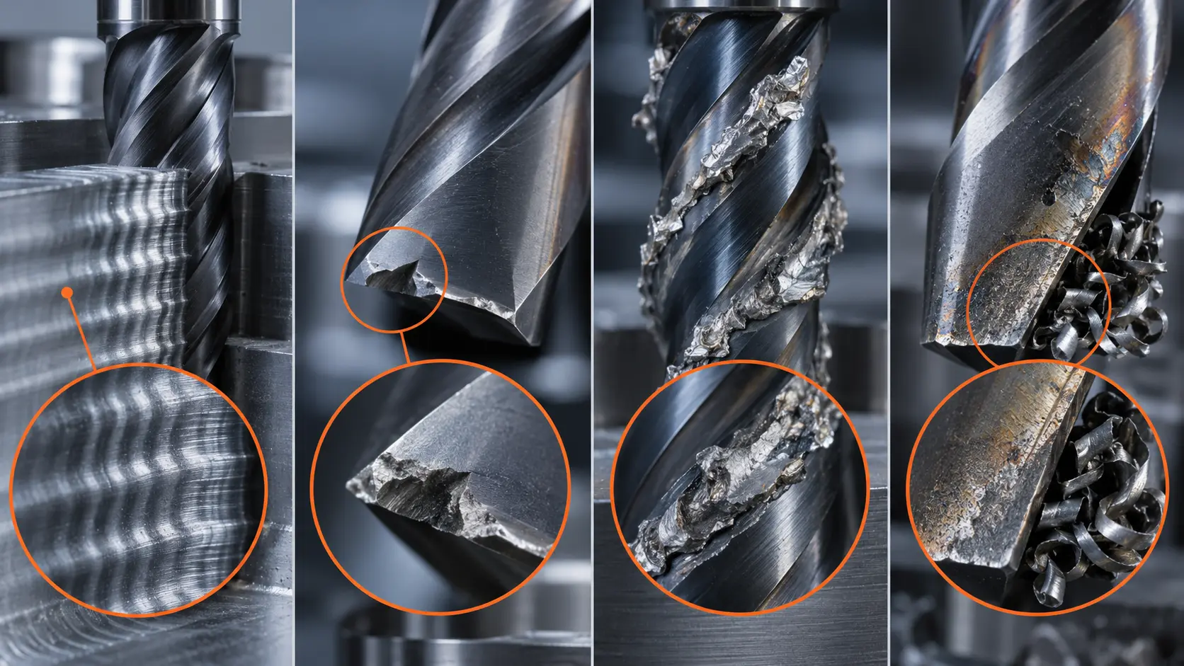
Common Carbide End Mill Selection Mistakes
| Observed Problem | Possible Selection or Setup Cause | First Checks |
|---|---|---|
| Chatter marks | Excessive reach, weak setup, unsuitable engagement, or harmonic excitation | Overhang, holder, workholding, toolpath, speed, and variable geometry |
| Chipped corners | Sharp corner overloaded, runout, impact, or unstable entry | Corner condition, runout, entry method, chip recutting, and edge strength |
| Built-up edge | Material adhesion, unsuitable coating, heat, or rubbing | Edge sharpness, coating compatibility, chip load, coolant, and flute finish |
| Rapid flank wear | Unsuitable grade or coating, abrasive material, or excessive heat | Material grade, hardness, cutting conditions, and wear pattern |
| Chip packing | Too many flutes, deep slot, poor evacuation, or recutting | Flute space, step-down, coolant or air, and pocket clearing |
| Tool pullout | Insufficient holder grip or high axial force | Holder condition, shank, clamping method, and programmed load |
Avoid changing several variables at once. If tool life falls suddenly, first measure runout, inspect the holder and workholding, examine the wear location, and confirm that the material lot and program have not changed. Replacing the coating while leaving a damaged collet in service will not solve the underlying problem.
How to Validate an End Mill Before Batch Production
- Confirm the workpiece. Record the material grade, hardness, stock condition, and any abrasive or interrupted features.
- Define the operation. State whether the tool will slot, shoulder, rough, finish, plunge, ramp, or machine a three-dimensional contour.
- Check the tool and holder. Inspect the cutting edges, shank, collet or holder, grip length, and measured runout.
- Start from application data. Use the exact tool supplier's speed, feed, and engagement guidance rather than a value for a visually similar cutter.
- Run a controlled first part. Use the planned machine, workholding, coolant, program, and material.
- Inspect the result. Check dimensions, surface finish, burrs, spindle load, sound, chip form, and early edge wear.
- Adjust one variable at a time. Record each change so the accepted process can be repeated.
- Release production after validation. Define tool-life and inspection intervals appropriate to the part risk.
For repeat production, keep a process record that links the tool specification to the approved holder, overhang, offsets, coolant condition, toolpath, and inspection result. This makes future troubleshooting faster than relying on the tool description alone.
Information to Provide When Requesting a Carbide End Mill
A useful tooling recommendation or quotation needs more than a diameter and quantity. Send ZIROOTOOLS the following information:
- Workpiece material, grade, and hardness
- Slotting, side milling, roughing, finishing, profiling, ramping, or plunging requirement
- Tool diameter, shank diameter, cutting length, and overall length
- Required corner radius or ball nose profile
- Preferred flute count or current tool specification
- Coating preference, if already validated
- Machine, spindle, holder, coolant, and workholding information
- Axial and radial depth of cut
- Part drawing, STEP file, or feature sketch
- Current problem, such as chatter, short life, chip packing, or poor finish
- Trial and production quantities
These details help distinguish a standard solid carbide end mill requirement from an application that may benefit from a custom diameter, reach, radius, flute arrangement, or geometry.
Frequently Asked Questions
What is a carbide end mill used for?
A carbide end mill is used on milling machines and machining centers for operations such as slotting, shoulder milling, pocketing, contouring, profiling, roughing, and finishing. The exact capability depends on its profile, flute geometry, dimensions, and whether it is designed for axial entry.
Is carbide better than HSS for end mills?
Carbide offers higher stiffness, wear resistance, and cutting-speed potential in a stable CNC process. HSS is tougher and may suit less rigid machines, interrupted loading, special shapes, or low-volume work. Compare the complete process and cost per part rather than assuming one material is always better.
How many flutes should a carbide end mill have?
Choose the flute count from the workpiece material, chip volume, and engagement. Fewer flutes provide more chip space; more flutes provide more cutting edges and usually a stronger core. Full slotting typically needs more evacuation capacity than light side milling.
What carbide end mill is suitable for aluminum?
Look for a sharp cutting edge, sufficient chip space, smooth flute surfaces, and a coating or uncoated design compatible with aluminum. Two- and three-flute designs are common starting points, but the exact choice depends on slotting, side milling, tool diameter, machine, and coolant method.
What end mill should you use for stainless steel?
Select a tool intended for the stainless grade and hardness, with stable edge geometry, suitable coating, and adequate chip control. Avoid dwelling and rubbing, maintain consistent chip load, and verify that the setup and coolant can control heat and work hardening.
What is the difference between square and ball nose end mills?
A square end mill is generally used for flat floors, slots, shoulders, and walls. A ball nose end mill is used for curved surfaces and three-dimensional contours. The ball's effective cutting diameter changes along its radius, which affects toolpath and surface speed.
Does every carbide end mill need a coating?
No. An uncoated, sharp tool can be suitable for some nonferrous applications. A coating should be selected for the workpiece, carbide substrate, edge geometry, heat, wear mechanism, and coolant condition. It cannot compensate for poor runout or chip evacuation.
Why does a carbide end mill chatter?
Possible causes include excessive overhang, weak workholding, holder runout, unsuitable speed, excessive engagement, tool deflection, or repeated cutting-force harmonics. Check the complete setup before replacing the tool based only on flute count or coating.
Can a carbide end mill plunge into material?
Only if its end geometry is designed to cut at the center and the supplier permits the intended entry method. Some tools ramp or helical-interpolate effectively but are not suitable for a straight axial plunge. Confirm the exact tool specification.
What information is needed for a custom carbide end mill?
Provide the material and hardness, operation, diameter, cutting length, overall length, shank, reach, corner form, flute requirements, machine, holder, coolant, drawing, current problem, and quantity. Do not rely on a sample photo when critical dimensions can be supplied.
Final Carbide End Mill Selection Checklist
- Confirm the exact material grade and hardness.
- Define the milling operation and engagement.
- Select the required square, ball nose, corner radius, or roughing profile.
- Balance flute count against chip space and edge count.
- Match the carbide grade, edge geometry, and coating to the application.
- Use the largest practical diameter and shortest practical reach.
- Check the machine, holder, runout, coolant, and workholding.
- Validate the supplier's starting data on a controlled first part.
- Inspect dimensions, finish, chips, load, and wear before batch production.
The right carbide end mill is the one that matches the material, operation, feature geometry, and actual machining system. For a tooling review or quotation, send ZIROOTOOLS your workpiece information, drawing, tool dimensions, machine setup, current cutting conditions, application problem, and required quantity.