Choosing among the many types of wood router bits is not simply a matter of matching a bit name to a cut. Buyers researching “wood router bits types” need more than a list of names. The correct tool must suit the required profile, workpiece material, machine, chip direction, and finish on the top and bottom surfaces.
A straight bit may be suitable for a basic groove, while a spiral bit can provide more continuous cutting and controlled chip movement. A downcut bit may protect the visible top face of a panel, whereas a compression bit is often considered when both faces of a laminated board must remain clean. Selecting the wrong geometry can contribute to tear-out, burning, chip buildup, chatter, poor dimensions, or premature tool wear.
This guide explains the main wood router bit types, how their cutting directions differ, which factors matter for solid wood and engineered panels, and what professional buyers should confirm before ordering standard or custom tooling.
What Is a Wood Router Bit?
A wood router bit is a rotating cutting tool used to remove material, form edges, cut grooves, copy profiles, create joints, or engrave wood and wood-based panels. Router bits may be used in handheld routers, router tables, or CNC routers, but compatibility should never be assumed from appearance alone.
The main parts and dimensions of a router bit include:
- Cutting edge: the sharpened portion that removes material.
- Flute: the channel beside the cutting edge that provides space for chips.
- Cutting diameter: the diameter of the profile or path produced by the bit.
- Cutting length: the usable axial length of the cutting edge.
- Shank: the cylindrical section held by the router collet or CNC toolholder.
- Bearing: a guide fitted to some profile bits so the tool can follow an edge or template.
- Profile: the cutting-edge shape that determines the finished geometry.
In supplier catalogs, related tools may be described as woodworking router bits, CNC router cutters, woodworking milling cutters, engraving bits, or profile cutters. Buyers should compare the drawing and dimensions rather than relying only on the product name.
Quick Comparison of the Main Types of Wood Router Bits
| Router bit type | Main function | Typical applications | Key selection point |
|---|---|---|---|
| Straight bit | Straight-sided material removal | Grooves, dados, mortises, pockets | Diameter, cutting length, chip clearance |
| Flush trim bit | Copies a template or reference edge | Panel trimming, laminate trimming, duplicate parts | Bearing position and cutting length |
| Rabbeting bit | Cuts a shoulder or step along an edge | Cabinets, frames, back panels | Bearing diameter and rabbet depth |
| Chamfer bit | Produces an angled edge | Bevels, edge preparation, decoration | Included angle and cutting depth |
| Roundover bit | Produces a convex radius | Furniture edges, shelves, countertops | Radius and workpiece thickness |
| Cove or core box bit | Produces a concave profile or round-bottom groove | Decorative edges, fluting, carving | Radius and depth per pass |
| Roman ogee bit | Produces a compound decorative profile | Cabinet doors, molding, furniture | Profile size and stock thickness |
| Dovetail bit | Produces angled joint geometry | Drawers, boxes, sliding dovetails | Angle, diameter, and jig compatibility |
| V-groove bit | Cuts a V-shaped groove | Lettering, signs, folding grooves, decoration | Angle, tip condition, and depth |
| Keyhole bit | Creates an undercut hanging slot | Wall-mounted products and displays | Entry path and slot dimensions |
| Spiral bit | Uses a helical edge for continuous cutting | CNC profiling, pockets, grooves | Upcut, downcut, or compression geometry |
| Compression bit | Combines opposite cutting directions | Double-sided laminated panels | Cut depth must engage both cutting zones |
12 Common Wood Router Bit Types and Their Uses
1. Straight Router Bits
Straight bits have cutting edges that run parallel to the tool axis. They are widely used for grooves, dados, mortises, pockets, and general material removal. They are easy to recognize, but the correct diameter and cutting length still depend on the width and depth of the feature.
Compared with a spiral bit, a conventional straight bit does not produce the same helical chip movement. For deeper grooves or production routing, buyers should consider how chips will leave the cut and whether multiple passes are required. A long cutting edge should not be selected unless the application actually needs it, because tool projection and rigidity also affect cutting stability.
2. Flush Trim Router Bits
A flush trim bit uses a bearing to follow a template, finished edge, or reference surface. It is commonly used to trim laminate, duplicate shaped parts, or bring one panel edge flush with another.
Top-bearing and bottom-bearing designs suit different template positions and feed setups. Before ordering, confirm where the reference surface will be located, how thick the material is, and whether the cutting edge can cover the complete workpiece thickness. The bearing must remain clean and rotate freely; a damaged or contaminated bearing can affect the finished edge.
3. Rabbeting Bits
Rabbeting bits cut a rectangular step along the edge of a workpiece. Rabbets are frequently used in cabinet backs, frames, boxes, and other assemblies where one component must overlap or seat into another.
On bearing-guided rabbeting bits, the difference between the cutting diameter and bearing diameter helps determine the rabbet width. Buyers should therefore specify the required shoulder geometry rather than ordering by a general product name. Depth may be controlled by the machine setup or router base.
4. Chamfer Bits
Chamfer bits cut an angled face along an edge. They can remove a sharp corner, prepare an edge for assembly, or create a visible decorative bevel. The result depends on the bit angle, cutting depth, bearing arrangement, and position relative to the workpiece.
A small change in height can alter the apparent width of the chamfer, so production users should document setup dimensions when consistent parts are required. The stock thickness must also provide enough support for the intended profile.
5. Roundover Bits
Roundover bits create a convex radius and are common in furniture, shelving, countertops, handles, and exposed wooden components. The radius should be selected according to the workpiece thickness and desired edge appearance.
Setting the bit too high or too low may leave a step or fillet beside the rounded portion. When matching an existing part, provide a drawing, radius measurement, or physical sample instead of describing the edge only as “rounded.”
6. Cove and Core Box Bits
Cove bits create a concave edge profile, while core box bits are commonly used for round-bottom grooves, fluting, lettering, and decorative carving. Although their profiles can look similar in a catalog image, the intended cutting path and contact with the workpiece may differ.
Wide or deep concave profiles should not automatically be completed in one pass. Pass depth, feed, speed, workholding, and machine rigidity must be considered together to reduce heat and cutting load.
7. Roman Ogee Bits
Roman ogee bits form a compound decorative edge, often combining convex and concave curves. They are used for cabinet doors, furniture components, trim, and molding.
Because the visual result depends on the full profile, buyers should verify the profile drawing, radius values, overall cutting height, bearing diameter, and the amount of material that will remain after machining. Two bits sold under similar names can produce visibly different profiles.
8. Dovetail Bits
Dovetail bits form angled sides used in dovetail joints, drawer construction, boxes, and sliding dovetails. Important specifications include the angle, cutting diameter, cutting height, shank size, and compatibility with any jig or template system.
Do not assume that two bits with the same nominal angle are interchangeable. Jig geometry and cutting diameter can affect joint fit. Trial cuts in representative material are advisable before a production batch.
9. V-Groove Bits
V-groove bits are used for signmaking, engraving, decorative lines, folding grooves, and chamfer-like features. The included angle and cutting depth determine the width of the groove at the material surface.
For CNC engraving, tip condition, tool runout, workpiece flatness, and programmed depth all influence line consistency. A fine tip can produce detailed work but may be more sensitive to cutting load and setup errors.
10. Keyhole Bits
Keyhole bits create a narrow entry slot with a wider undercut section. They are used for concealed hanging features in plaques, frames, displays, and other wall-mounted wooden products.
The toolpath usually requires a controlled plunge, lateral movement, and return before retraction. The machine, router, and workholding must support that movement safely. Buyers should provide the head diameter, neck diameter, slot length, and required depth.
11. Spiral Router Bits
Spiral router bits use helical cutting edges rather than straight edges. They are widely used for CNC profiling, pocketing, slotting, and cutting sheet goods. The helix can move chips upward or downward, which changes chip evacuation and the surface that receives the strongest cutting support.
“Spiral bit” is therefore not a complete specification. A buyer must still choose between upcut, downcut, and compression geometry, as well as the diameter, flute count, cutting length, shank, and material.
12. Compression Router Bits
A compression router bit combines an upcut section near one end of the cutting edge with a downcut section along the remaining portion. When correctly engaged, the geometry directs cutting forces toward the center of the panel and can help protect both faces of a double-sided laminated board.
However, a compression tool only works as intended when the programmed cutting depth places the top and bottom faces in the correct cutting zones. If the first pass does not extend beyond the transition between the two geometries, one face may still be cut by the wrong section. The transition length should therefore be checked against the planned depth of cut.
Upcut vs Downcut vs Compression Router Bits
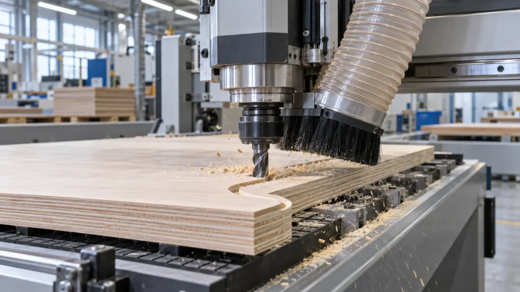
| Geometry | Chip direction | Surface tendency | Typical use | Main consideration |
|---|---|---|---|---|
| Upcut | Moves chips upward | Often supports chip evacuation; the top edge may require more attention | Grooves, pockets, through-cuts where evacuation is important | Top-face tear-out and workpiece holding |
| Downcut | Pushes chips downward | Can help protect the top face | Shallow grooves and visible top surfaces | Chip packing, heat, and bottom-face quality |
| Compression | Directs cutting toward the panel center | Designed to support both faces when correctly engaged | Double-sided plywood and laminated panels | Transition length and actual cutting depth |
Upcut Router Bits
An upcut bit lifts chips from the cutting zone. This can be useful in slots and pockets where chip evacuation is difficult. The upward action can also pull fibers at the top face, especially in materials prone to splintering. Secure workholding is important because the axial cutting force may tend to lift the workpiece.
Downcut Router Bits
A downcut bit pushes chips toward the bottom of the cut and can help maintain a cleaner visible top edge. This geometry may be useful for shallow grooves or parts where the upper surface is the priority. In deep slots, however, chips may have less room to escape, making dust extraction, pass depth, heat control, and toolpath strategy particularly important.
Compression Router Bits
Compression bits are often selected for panels that have finished surfaces on both sides. They are not automatically the best choice for every operation. Thin workpieces, shallow first passes, limited machine rigidity, or an unsuitable transition length can prevent the geometry from working as intended. Review the tool drawing and CAM strategy together.
How to Choose Router Bits for Different Wood Materials
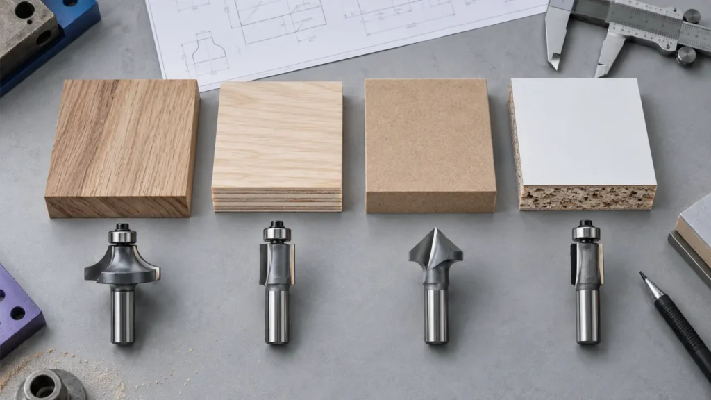
| Material | Common selection direction | Main risks to check |
|---|---|---|
| Solid wood | Sharp straight or spiral geometry selected for the cut and grain direction | Tear-out, burning, resin buildup, grain reversal |
| Plywood | Upcut, downcut, or compression according to the priority surface | Veneer splintering and voids within the panel |
| MDF | Geometry with adequate chip and dust clearance | Fine dust, heat, abrasive wear, fuzzy edges |
| Particleboard | Tooling selected for abrasive composite material and edge requirements | Rapid wear, edge breakdown, chip packing |
| Laminated panel | Downcut or compression where surface protection is critical | Chipping of the decorative layer on one or both faces |
Solid Wood
Solid wood varies by species, density, grain direction, resin content, and moisture condition. A setup that works well in one hardwood may burn or tear another material. Sharpness, cutting direction, chip load, tool projection, and the direction of grain around curved parts all influence the result.
When machining a complex profile, consider whether the tool will encounter changing grain direction. A smaller finishing allowance or a separate finishing pass may improve consistency, depending on the machine and part geometry.
Plywood
Plywood contains alternating veneer layers, and the outer veneer may splinter if it lacks support during cutting. Choose upcut, downcut, or compression geometry according to whether the top face, bottom face, or both faces must remain clean. Internal voids and adhesive layers can also affect the cut, so sample testing should use the actual panel grade.
MDF
MDF machines without natural grain, but it creates fine dust and can be abrasive. Dust extraction, flute space, tool cleanliness, and cutting temperature require attention. A worn tool may leave fuzzy edges or generate additional heat. Production buyers should assess performance over a representative run rather than judging only the first part.
Particleboard and Laminated Panels
Particleboard and similar engineered panels can be abrasive and may have fragile decorative surfaces. For two-sided laminated boards, compression geometry is often considered to reduce chipping on both faces. The tool must be matched to panel thickness and programmed depth so the compression transition sits inside the material rather than at a finished surface.
Plastic-Laminated Wood Products
A laminated workpiece combines the behavior of the surface layer with that of the wood-based core. The best tool for an uncoated board may not give the same result after a decorative film or plastic laminate is added. Provide the complete material construction when asking a supplier for a recommendation.
Router Bit Material: Carbide, HSS, or PCD?
High-Speed Steel
High-speed steel can provide a keen cutting edge and may suit some lighter woodworking tasks. Its suitability depends on the material and production conditions. A lower initial tool price does not necessarily produce the lowest cost per finished part if tool changes or edge deterioration interrupt production.
Carbide Router Bits
Carbide is widely used for woodworking and composite panel tools because it offers useful wear resistance while maintaining a cutting edge. Products may use solid-carbide construction or carbide cutting edges joined to another tool body. These designs should not be treated as identical; diameter, profile, cutting load, repair strategy, and application all matter.
PCD Router Bits
Polycrystalline diamond tooling may be evaluated for abrasive materials and stable, high-volume production. It generally involves different cost, edge geometry, repair, and application considerations from conventional carbide tooling. Before specifying PCD, buyers should provide the exact panel type, operation, volume, required finish, and machine conditions. Availability and custom capability must be confirmed with the supplier.
Seven Specifications to Confirm Before Ordering
- Workpiece material: identify the species or exact panel construction, including laminate layers.
- Machine and spindle: provide the router or CNC model, power, speed range, and toolholding arrangement when relevant.
- Collet and shank size: confirm whether the system uses metric or inch dimensions. Similar-looking sizes are not automatically interchangeable.
- Cutting diameter: specify the groove width or finished profile, not only a general tool name.
- Cutting and overall length: make sure the cutting edge covers the application without unnecessary tool projection.
- Required edge quality: state whether the top, bottom, or both faces will remain visible.
- Production conditions: share the toolpath, expected volume, dust extraction, and current problem if replacing an existing tool.
For a custom profile, include a dimensioned drawing. A photo is useful for context, but it usually cannot define angles, radii, tolerances, or cutting length accurately enough by itself.
How Flute Count Affects Cutting Performance
One-Flute Bits
A single-flute tool provides a relatively large flute space for chips. This can be useful where evacuation is the main constraint or when the available feed and spindle speed favor fewer cutting-edge engagements per revolution. The final choice still depends on diameter, material, machine stability, and the required finish.
Two-Flute Bits
Two-flute router bits are a common general-purpose choice because they can balance chip space, edge engagement, and surface finish across many woodworking operations. That does not mean every two-flute tool performs the same; helix, edge preparation, carbide grade, runout, and cutting parameters remain important.
Multi-Flute Bits
Additional flutes increase the number of cutting-edge contacts per revolution but reduce the space available between flutes. If feed is too low for the selected speed and flute count, the edge may rub rather than form an efficient chip. More flutes are therefore not automatically better. Flute count, spindle speed, feed, and chip evacuation should be evaluated as one system.
Common Router Bit Problems and Troubleshooting
| Problem | Possible causes | What to check |
|---|---|---|
| Burn marks | Dull edge, excessive rubbing, poor chip removal, unsuitable feed/speed relationship | Tool sharpness, resin buildup, feed, speed, pass depth, dust extraction |
| Top-face tear-out | Upward cutting action, unsupported fibers, dull tool | Cutting direction, downcut option, edge condition, finishing allowance |
| Bottom-face chipping | Geometry does not support the lower face | Upcut/compression choice, spoilboard support, through-cut depth |
| Fuzzy edge | Worn tool, unsuitable geometry, flexible fibers, unstable setup | Edge condition, material, runout, finishing pass |
| Chip buildup | Insufficient flute space or extraction, deep slot, resin | Flute design, pass strategy, cleaning, airflow, chip path |
| Chatter marks | Excessive projection, runout, weak workholding, tool deflection | Collet condition, shank cleanliness, projection, machine rigidity |
| Bit breakage | Excessive load, collision, inadequate chip clearance, incorrect setup | Toolpath, pass depth, feed/speed, holder, material inclusions |
| Rapid wear | Abrasive material, heat, contamination, unsuitable tool material | Panel composition, tool grade, dust removal, cutting parameters |
| Poor dimensions | Runout, deflection, incorrect tool diameter, machine error | Measured diameter, holder condition, calibration, toolpath compensation |
Troubleshooting should change one controlled factor at a time. Replacing a tool, changing speed, changing feed, and altering depth simultaneously makes it difficult to identify the real cause. Record the machine, material batch, tool specification, and parameter changes for repeatable production.
Handheld Router Bits vs CNC Router Bits
A handheld router depends heavily on operator control, router base stability, feed direction, and the use of fences, bearings, or templates. A CNC router controls the toolpath through programmed machine movement and may support more repeatable pocketing, profiling, ramping, and multi-pass strategies.
However, a bit should not be moved between machines simply because its shank appears to fit. Confirm:
- the shank matches the actual collet size;
- the machine can operate within the tool manufacturer’s limits;
- the tool is suitable for plunging if the programmed path requires it;
- the cutting diameter and projection are safe for the machine and operation;
- the feed direction and workholding account for cutting forces;
- the dust extraction system can remove the resulting chips.
For production CNC work, a complete tool drawing and documented setup provide a more reliable basis for repeat orders than a marketplace photo or informal product name.
How B2B Buyers Can Evaluate a Router Bit Supplier
Professional sourcing should examine more than unit price. A supplier should be able to clarify the application, interpret dimensions, and identify missing information before production. Useful evaluation points include:
- Specification completeness: Are cutting diameter, cutting length, shank, overall length, flute count, geometry, and material clearly defined?
- Application communication: Does the supplier ask about the workpiece, machine, operation, and required finish?
- Drawing capability: Can standard or custom profiles be confirmed with a dimensioned drawing?
- Quality control: Are critical dimensions and visual conditions checked consistently?
- Sample validation: Is there a process for testing the selected geometry in representative material before scaling?
- Batch consistency: Are repeat-order specifications traceable and clearly recorded?
- Packaging: Are cutting edges protected against contact and transport damage?
- Technical follow-up: Can the supplier help separate tool wear, parameter, workholding, and material problems?
ZIROO TOOLS provides woodworking router bit and woodworking milling cutter categories and accepts OEM/ODM inquiries based on drawings, specifications, and technical requirements. Final material, geometry, tolerance, quantity, and delivery details should be confirmed for each project rather than assumed from a general catalog description.
Information to Send When Requesting a Quote
A detailed inquiry helps the supplier recommend or design the correct tool more efficiently. Include as much of the following information as possible:
- material name, species, or panel construction;
- workpiece dimensions and thickness;
- handheld router, router table, or CNC machine model;
- spindle and collet information;
- required shank diameter;
- cutting diameter, cutting length, and overall length;
- profile drawing, CAD file, or clear sample images;
- whether the top, bottom, or both faces are visible;
- current tool and the problem that needs to be solved;
- estimated order quantity and delivery destination.
Need help selecting a woodworking router bit? Send your material, machine information, required cutting dimensions, drawing, quantity, and delivery destination to contact ZIROO TOOLS for application review and quotation.
Frequently Asked Questions
What are the most commonly used types of wood router bits?
Common types include straight, flush trim, rabbeting, chamfer, roundover, cove, core box, Roman ogee, dovetail, V-groove, keyhole, spiral, and compression bits. The most useful type depends on whether the job involves grooves, edge profiles, joinery, trimming, engraving, or CNC panel cutting.
What is the difference between a straight bit and a spiral bit?
A straight bit generally uses cutting edges parallel to the tool axis. A spiral bit uses helical edges that create more continuous cutting and direct chips upward or downward. Spiral geometry can be valuable for CNC grooves, pockets, and profiling, but the correct helix direction must be selected for the surface and chip-control requirements.
Should I use an upcut or downcut bit for plywood?
Choose according to the priority surface and the operation. An upcut bit generally favors chip evacuation but may require more attention to the top veneer. A downcut bit can help protect the top face but may pack chips into a deep groove. If both faces are finished, a correctly selected and engaged compression bit may be more appropriate.
When should I use a compression router bit?
Compression bits are commonly considered for through-cutting plywood or laminated panels when both faces require a clean edge. Confirm the workpiece thickness, first-pass depth, upcut-section length, and toolpath so both cutting directions engage the intended surfaces.
What router bit works best for MDF?
There is no single best bit for every MDF operation. Select the profile and cutting direction for the feature, then evaluate flute space, dust extraction, carbide or other tool material, edge sharpness, and production volume. MDF dust and abrasive wear should be included in the tooling decision.
How do I choose the correct router bit shank size?
Use the size specified for the router collet or CNC toolholder. Confirm whether the system is metric or inch-based; for example, dimensions that appear close should not be treated as interchangeable. The shank must be clean, undamaged, and correctly clamped according to the equipment instructions.
Can CNC router bits be used in a handheld router?
Only when the bit manufacturer’s requirements, shank size, operating limits, cutting action, and intended feed method are compatible with the handheld router. Some CNC tools or programmed operations are not suitable for handheld use. Verify the complete application rather than relying on shank fit alone.
What information is needed for a custom wood router bit?
Provide a dimensioned profile drawing, workpiece material, machine and holder information, shank size, cutting diameter, cutting length, overall length, required edge quality, quantity, and sample images if available. Describe the current machining problem and any tool already being used.
Conclusion
The most effective way to compare the different types of wood router bits is to begin with the machining task, then match the cutting direction to the material and required surface quality. After that, verify the shank, diameter, cutting length, flute count, tool material, machine conditions, and production volume.
Straight and profile bits solve specific groove and edge-forming tasks. Upcut and downcut spiral bits manage chips and surface support differently, while compression tools can help with double-sided panels when the cutting zones are correctly engaged. No geometry can compensate for an incompatible collet, unstable workholding, excessive runout, a worn edge, or unsuitable machining parameters.
For a standard or custom woodworking cutting tool inquiry, send ZIROO TOOLS your material details, machine information, dimensioned drawing, required finish, quantity, and delivery destination. A complete application description provides the best foundation for tool selection and quotation.