For a standard 1/4-20 UNC cutting tap, start with a #7 drill bit. Its nominal diameter is 0.2010 inch (5.105 mm). If numbered drills are unavailable, a 5.1 mm drill is the closest common metric equivalent, while 13/64 inch (0.2031 inch) is a slightly larger fractional alternative.
That answer applies to a conventional cutting tap. It should not be carried over to a form or roll tap. A form tap displaces material instead of cutting it, so it normally requires a larger pre-drilled hole specified by the tap manufacturer.
For a one-off, the chart value may be enough to get started. In CNC production, it is only the first input. Tap style, hole type, material, tool runout, drill wear, lubrication and the measured hole diameter all affect the result. This guide explains how to select the starting size, recognize the exceptions and verify the first part before a full batch is machined.
Quick Answer: Use a #7 Drill for a Standard 1/4-20 Cutting Tap
| Application | Starting drill size | Decimal size | Important note |
|---|---|---|---|
| 1/4-20 UNC cutting tap | #7 | 0.2010 in | Standard chart value |
| Metric approximation | 5.1 mm | 0.2008 in | Closest common metric size |
| Fractional alternative | 13/64 in | 0.2031 in | Slightly larger than #7 |
| 1/4-20 form or roll tap | Follow tap data | Often larger | Do not use a cutting-tap chart |
A #7 drill provides a practical starting balance between thread engagement and tapping load for a standard 1/4-20 cutting tap. However, do not approve a production process from the drill marking alone. Measure the hole, tap a test piece and inspect the finished thread.
Decision rule: Use #7 as the starting point for a conventional 1/4-20 UNC cutting tap. Stop and check the tap maker's data if the tool forms rather than cuts the thread.
What Does 1/4-20 UNC Mean?
The designation contains three pieces of information.
- 1/4 is the nominal major diameter of the thread: 0.250 inch.
- 20 means 20 threads per inch (TPI).
- UNC means Unified National Coarse.
The pitch is the axial distance between adjacent thread crests. For a 20-TPI thread, the pitch is 1/20 inch, or 0.050 inch. The tap drill must be smaller than the 0.250-inch major diameter so that material remains for the internal thread.
Do not select a drill from the nominal diameter alone. A 1/4-28 UNF thread has the same nominal major diameter but a finer pitch and a different tap-drill size.
| Thread | Series | TPI | Common cutting-tap drill |
|---|---|---|---|
| 1/4-20 | UNC | 20 | #7 (0.2010 in) |
| 1/4-28 | UNF | 28 | #3 (0.2130 in) |
Mixing these specifications can leave too much or too little material for the tap. Confirm the full marking on the drawing and the tool before drilling.
The Tap-Type-First Rule
Many tap-drill charts provide the right answer but omit the condition attached to it. In this guide, we call this decision process the Tap-Type-First Rule.
Step 1: Confirm the complete thread specification
Check the nominal diameter, threads per inch and thread series. If the drawing specifies a thread class, inspection requirement or minimum full-thread depth, record those items before selecting the process.
Step 2: Identify how the tap produces the thread
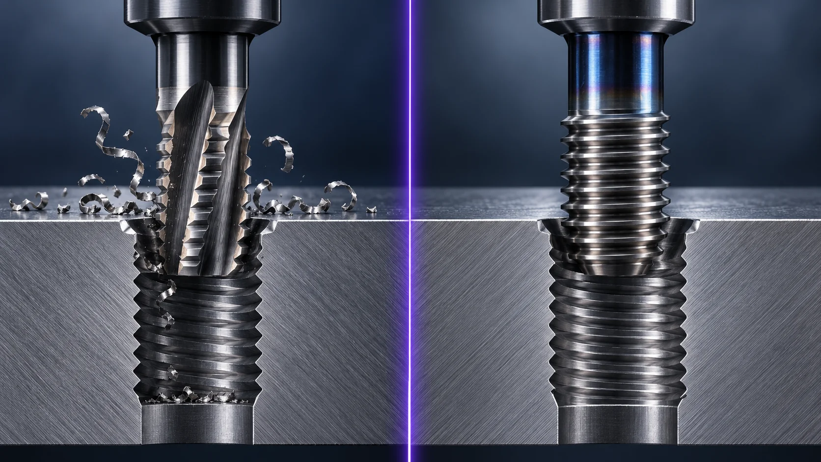
A cutting tap removes material and produces chips. A form tap, also called a roll tap, moves material into the thread profile without cutting chips. These two processes do not begin with the same hole size.
Step 3: Verify the hole and the finished thread
Measure the drilled hole instead of assuming it matches the nominal drill diameter. Tap one test part, inspect it with the gauge required by the drawing and record the accepted setup.
The Tap-Type-First Rule prevents the most consequential error in this job: using a familiar cutting-tap value for a forming operation.
Cutting Tap vs. Form Tap Drill Size
| Factor | Cutting tap | Form or roll tap |
|---|---|---|
| Thread-making method | Removes material | Displaces material |
| Chips | Produces chips | Chipless process |
| Starting hole | Smaller | Generally larger |
| 1/4-20 reference | #7 / 0.2010 in | Use the tap maker's chart |
| Key process risk | Chip packing and edge breakage | Incorrect material flow or minor diameter |
| Material requirement | Broad, with the correct geometry | Material must be suitable for forming |
The difference is substantial. One Haas reference chart lists 5.8 mm as a starting point for a 1/4-20 roll tap, compared with approximately 5.1 mm for the common cutting-tap recommendation. This value should not replace the hole-size range supplied for the exact tap. Haas also states that material, hardness and tolerance may require adjustment.
That 5.8 mm value is not a universal prescription for every form tap. Tap geometry and the required finished minor diameter vary. Use the data supplied for the exact tap, then confirm the actual hole and finished thread.
Form tapping also depends on the workpiece's ability to deform without cracking or producing an unacceptable thread profile. When material suitability is uncertain, ask the tap supplier to review the grade, hardness and application.
Point to remember: “1/4-20” identifies the finished thread, not one universal pre-drill size for every tapping method.
Is 13/64 Inch Close Enough for a 1/4-20 Tap?
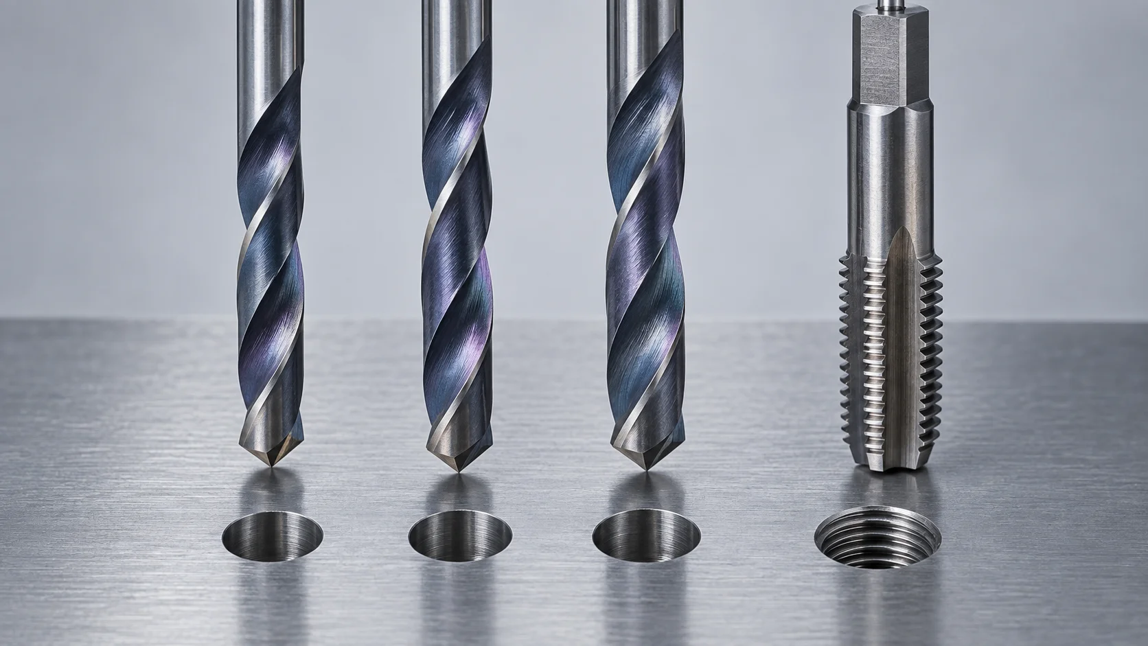
A 13/64-inch drill has a nominal diameter of 0.203125 inch. It is approximately 0.0021 inch larger than a #7 drill.
| Drill | Diameter, inch | Diameter, mm | Difference from #7 |
|---|---|---|---|
| 5.1 mm | 0.2008 | 5.100 | About 0.0002 in smaller |
| #7 | 0.2010 | 5.105 | Baseline |
| 13/64 in | 0.2031 | 5.159 | About 0.0021 in larger |
The fractional drill is commonly listed as the nearest convenient alternative. Because it creates a slightly larger nominal hole, it can reduce the amount of material removed by the tap and may lower tapping torque. The tradeoff is lower thread engagement.
Whether that tradeoff is acceptable depends on the drawing, thread class, material, loading and inspection requirement. It may be reasonable for a noncritical repair or a shop trial. It should not be accepted automatically for a controlled production part.
Do not describe 13/64 inch as identical to #7. For production, compare the measured holes, tap sample parts and verify the threads using the specified gauge.
Why the Actual Hole May Not Match the Drill Size
The size printed on a drill is an input. The machined hole is the result.
Drill and spindle runout
Runout can make the effective cutting path larger than the nominal tool diameter. Sources include the spindle, holder, collet, tool shank and setup. Haas specifically warns that drill runout affects actual hole size in form-tapping applications.
Drill wear and edge condition
A worn, chipped or built-up cutting edge can change cutting forces and hole quality. The hole may become oversized, tapered or out of round. Inspect the tool when a previously stable process begins producing inconsistent threads.
Workpiece material
Material affects cutting force, heat, chip shape and built-up-edge behavior. Stainless steel, mild steel and aluminum do not behave identically, but material alone does not justify changing the drill size. First review the tap data, thread requirement and measured result.
Feed, speed, coolant and hole depth
Poor chip evacuation, unstable feed, excessive heat or inadequate lubrication can damage both the drilled hole and the tap. Deep and blind holes are more sensitive because chips have less room to escape.
For a tight-tolerance process, a carbide drill or a drilled-and-reamed hole may provide better control than changing chart sizes by guesswork. You can also review ZIROOTOOLS' CNC cutting-tool range when planning related milling operations. The correct choice depends on the tolerance and production method.
Through Holes vs. Blind Holes
Hole type changes the chip-control problem.
| Hole type | Primary concern | Tap style often considered | Check before machining |
|---|---|---|---|
| Through hole | Push chips beyond the thread | Spiral-point cutting tap | Exit clearance and burr control |
| Blind hole | Remove chips away from the bottom | Spiral-flute cutting tap | Bottom clearance and usable thread depth |
| Form-tapped hole | Control material flow and minor diameter | Application-specific form tap | Material suitability and tap data |
A spiral-point tap generally pushes chips ahead of the tool, so it is commonly selected for through holes where chips can exit. A spiral-flute tap draws chips back toward the entrance and is often selected for blind holes.
For a blind hole, the drilled depth must include more than the required full-thread depth. Space is needed for the drill point, tap chamfer, incomplete threads and chips. The exact allowance depends on the drill and tap geometry, so avoid using a fixed universal extra-depth rule.
What Happens When the Tap Drill Is Too Small or Too Large?
| Condition | Likely result | What to check first |
|---|---|---|
| Hole too small | High torque, edge damage or tap breakage | Actual diameter, drill size, wear and runout |
| Hole too large | Reduced thread engagement | Drill selection and measured diameter |
| Hole tapered or out of round | Inconsistent thread and gauge results | Toolholding, alignment and drill condition |
| Chips trapped in a blind hole | Chipping, galling or breakage | Tap style, depth, lubrication and chip evacuation |
| Chart size is correct but tapping still fails | Process-specific problem | Material, tap geometry, alignment and machine settings |
The most expensive mistake is often discovered after batch production begins. A broken tap can stop the machine and damage a part. A large hole may pass unnoticed until thread inspection or assembly. Verify the process on the first piece, not after the batch.
If torque is high, do not immediately move to a larger drill. Confirm that the tool is a cutting tap, measure the existing hole and inspect chip evacuation, lubrication and alignment. Changing one variable without identifying the cause can replace one defect with another.
How to Verify a 1/4-20 Tapped Hole Before Batch Production
- Read the drawing. Confirm 1/4-20 UNC, thread class, full-thread depth and inspection requirement.
- Check the tap. Identify whether it is a cutting or forming tool and review its technical data.
- Select the starting drill. Use #7 for a conventional cutting tap unless the application data specifies otherwise.
- Measure the drilled hole. Use a suitable bore-measurement method or pin gauges where the tolerance requires them.
- Inspect the setup. Check toolholding, runout, drill condition, coolant delivery and chip evacuation.
- Tap a test part. Use the planned machine cycle and workpiece material.
- Gauge the thread. Apply the GO/NO-GO gauge or inspection method specified for the part.
- Record the approved process. Document the tools, settings, measured hole and inspection result.
- Monitor production. Recheck the process at an interval appropriate to tool wear and part risk.
A caliper is useful for many shop measurements but is not the best tool for confirming a small precision bore. Match the measurement method to the required tolerance.
1/4-20 Tap Drill Selection Checklist
Before drilling, confirm:
- ☐ The specification is 1/4-20 UNC, not 1/4-28 UNF or 1/4 NPT.
- ☐ The tap is a cutting tap or a form tap.
- ☐ The workpiece material and hardness are known.
- ☐ The hole is through or blind.
- ☐ Required full-thread depth and total drill depth are defined.
- ☐ The thread class and inspection method are known.
- ☐ The starting drill follows the exact tap data where required.
- ☐ The drilled hole is measured before tapping.
- ☐ Toolholding and runout are acceptable.
- ☐ Coolant, lubricant and chip evacuation suit the process.
- ☐ A first-piece thread is gauged before batch production.
Information to Send When Requesting Tooling Support
A useful tooling review needs more than the words “1/4-20 tap.” Send:
- Workpiece material and grade
- Material hardness, when known
- 1/4-20 UNC thread class
- Cutting tap or form tap
- Through hole or blind hole
- Hole depth and required full-thread depth
- Part drawing or STEP file
- CNC machine, holder and coolant arrangement
- Current drill and tap details
- Current failure, tool-life or inspection problem
- Trial and production quantities
When requesting a quote from ZIROOTOOLS, include your workpiece material, hole type, thread specification, drawing, machine information and required quantity. These application details will help determine whether a standard tool or a customized cutting-tool solution should be considered.
Frequently Asked Questions
What size drill bit is used for a 1/4-20 tap?
Use a #7 drill bit, 0.2010 inch or about 5.1 mm, as the standard starting size for a conventional 1/4-20 UNC cutting tap. If you are using a form or roll tap, use the hole size specified for that exact tap instead.
Can I use a 13/64-inch drill for a 1/4-20 tap?
13/64 inch is a common fractional alternative, but it is approximately 0.0021 inch larger than #7. It may reduce tapping load while also reducing thread engagement. Verify whether it meets the drawing and gauge requirements before using it in production.
What is the metric equivalent of a #7 drill bit?
A #7 drill is 0.2010 inch, equal to approximately 5.105 mm. A 5.1 mm drill is the closest common metric approximation.
Is a 1/4-20 tap UNC or UNF?
1/4-20 is a Unified National Coarse (UNC) thread with 20 threads per inch. The fine-thread version is 1/4-28 UNF.
Does a 1/4-28 tap use the same drill size?
No. A standard 1/4-28 UNF cutting tap commonly uses a #3 drill, 0.2130 inch. Always check the complete thread designation rather than the 1/4-inch nominal diameter alone.
Does a 1/4-20 form tap use a #7 drill?
Normally, no. A form tap displaces material and generally needs a larger starting hole than a cutting tap. Use the tap manufacturer's hole-size range. A public Haas chart lists 5.8 mm as one starting reference, but the exact tap data controls.
Why does my 1/4-20 tap keep breaking?
Possible causes include an undersized hole, chip packing, poor alignment, insufficient lubrication, incorrect tap style, unsuitable speed or feed, a worn tool, and using a cutting-tap hole size with a form tap. Measure the hole and inspect the full process before changing sizes.
Should I change the drill size for stainless steel?
Do not change it from material name alone. Review the exact tap maker's recommendation, material grade and hardness, hole type, lubrication and measured hole. Run and gauge a test part before approving production.
Final Recommendation
For a standard 1/4-20 UNC cutting tap, a #7 drill at 0.2010 inch is the normal starting point. A 5.1 mm drill is the closest common metric option. A 13/64-inch drill is slightly larger and should be treated as an alternative, not an identical replacement.
The exception matters: a form or roll tap requires a different, generally larger hole. Apply the Tap-Type-First Rule, measure the actual drilled hole and gauge the first tapped part before running a batch.
For a production inquiry, contact ZIROOTOOLS with the workpiece material, tap type, hole details, drawing, machine setup and quantity. Those inputs allow the tooling decision to be based on the process rather than a chart value alone.
References & Sources
- US Tap and Drill Bit Size Table — Bolt Depot.
- Tap and Drill Size Chart — American Fastener Technologies Corporation.
- Roll Tap Drill Size Chart — Haas Automation.
- Inch Form Tap Drill Size Chart — Haas Automation.
- Know the Drill — EMUGE-FRANKEN USA.