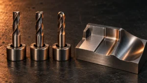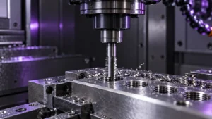
Choosing between different types of end mills starts with the feature you need to machine. A flat floor, curved mold surface, deep pocket, narrow slot, undercut, or thread each places different demands on a cutter. Tool catalogs classify cutters by end shape, machining purpose, reach, and specialized function, and those categories often overlap: a long-neck ball nose combines an end profile with an access design.
This guide separates those classification dimensions and connects them to machining tasks. You will see what square, ball nose, corner radius, chamfer, tapered, roughing, finishing, long-neck, micro, and specialty cutters are designed to do, where their geometry limits them, and what to check before ordering. The selection steps and supplier checklist are intended for CNC programmers, process engineers, machinists, shop managers, buyers, and distributors who need to describe a requirement clearly and compare a standard tool with a possible custom design.
Use the drawing and operation as your starting point, then check tool access, chip evacuation, rigidity, and finish requirements. Material, toolpath, machine, holder, and overhang all affect the result, so treat a cutter name as a starting point and confirm cutting data for the exact tool and setup.
Quick Reference: End Mill Types at a Glance
| Design dimension | End mill type | Typical use | Check before selection |
|---|---|---|---|
| Cutting-end shape | Square or flat end mill | Slots, pockets, flat floors, straight walls | Required internal corner and chip evacuation |
| Cutting-end shape | Ball nose end mill | Curved surfaces, 3D contours, mold cavities | Smallest surface radius, stepover, and finish target |
| Cutting-end shape | Corner radius or bull nose end mill | Shoulders, profiles, semi-finishing | Part radius and whether a flat floor is needed |
| Cutting-end shape | Chamfer or tapered end mill | Chamfers, angled walls, drafted features | Included angle, tip diameter, and access |
| Machining purpose | Roughing end mill | Higher stock removal before finishing | Stock allowance, machine rigidity, and chip control |
| Machining purpose | Finishing end mill | Final profile, surface, or dimensional pass | Toolpath, edge condition, runout, and required finish |
| Tool access | Long-neck or extended-reach end mill | Deep or obstructed features | Neck clearance, cutting length, overhang, and deflection |
| Tool size | Micro end mill | Small slots, ribs, cavities, and details | Runout, holder accuracy, entry path, and chip removal |
| Specialized function | Thread mill, T-slot, dovetail, or lollipop cutter | Threads, undercuts, or special profiles | Feature drawing and tool-specific programming |
These labels can overlap: a long-neck ball nose combines an end profile with an access design. Describe the feature first, then specify the geometry and clearance required.
How End Mill Types Are Classified
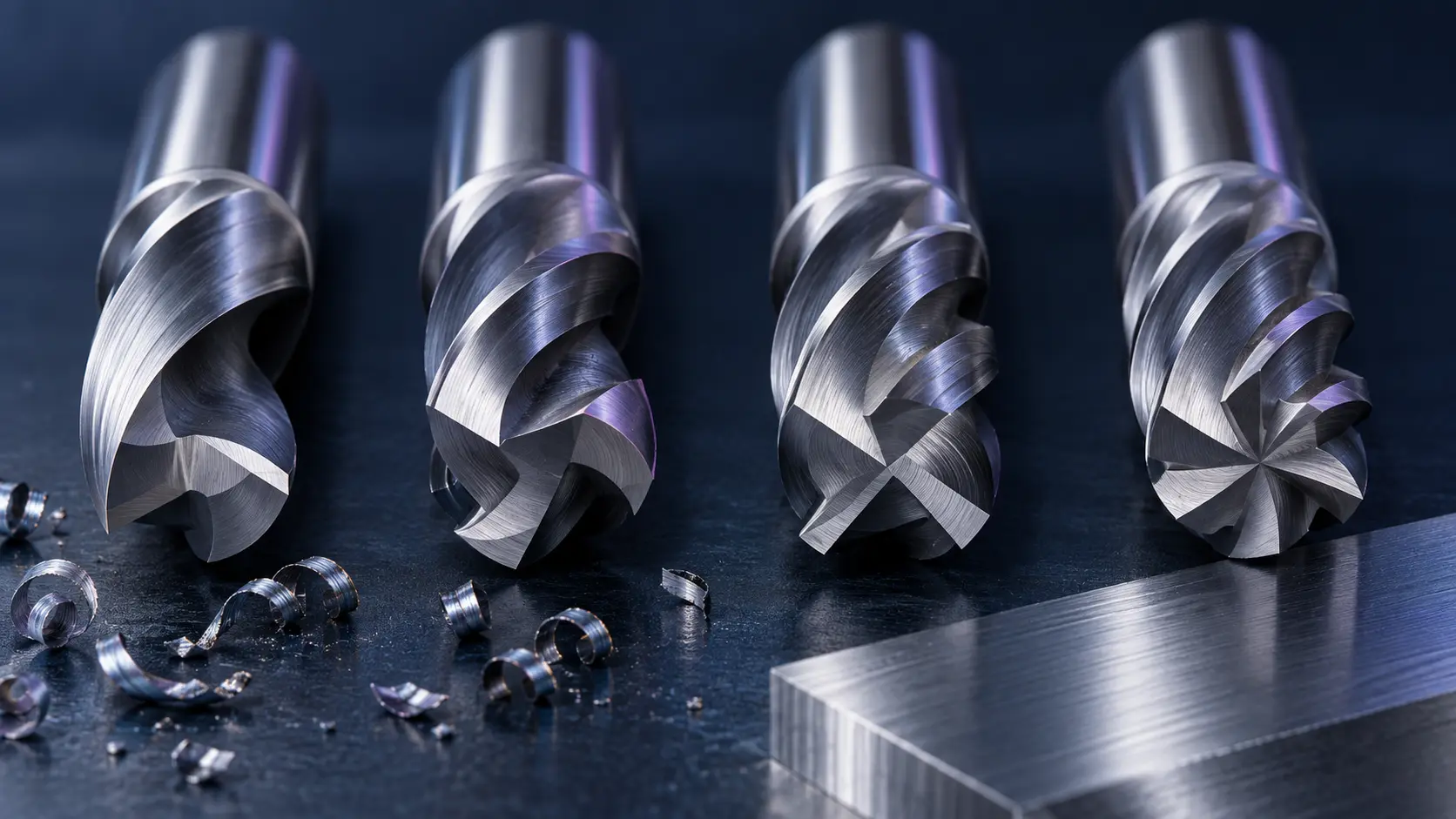
Before comparing end mill names, separate four questions:
- What shape does the cutting end need? This describes a square, ball nose, corner radius, chamfer, or other profile.
- What stage of machining is being performed? Roughing and finishing describe the tool’s intended role in a process.
- How does the tool reach the feature? Long-neck, reduced-neck, and extended-reach designs address clearance and access.
- What feature does the tool make? Thread mills, T-slot cutters, dovetail cutters, and lollipop tools are designed for particular geometries.
Flute count, helix, core size, and coating are additional specifications, not end shapes. Select them for the material and operation; our carbide end mill selection guide covers those factors in more detail.
Common End Mill Shapes and What They Machine
Square or Flat End Mills
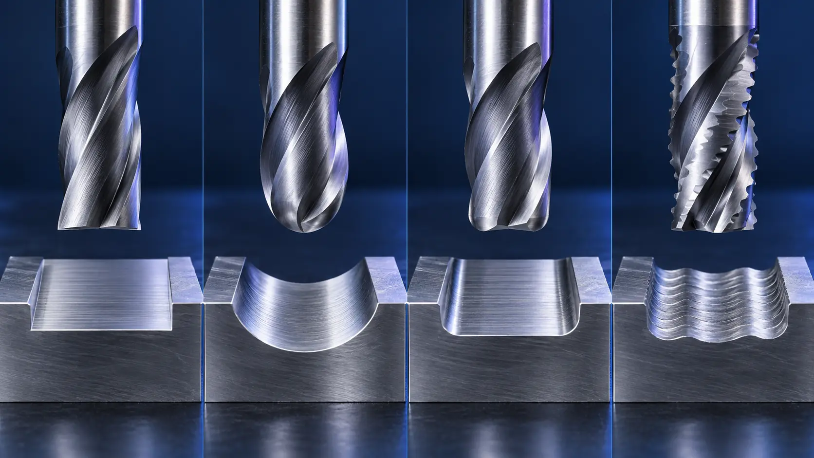
A square end mill, also called a flat end mill, has a nominally flat cutting end and a defined corner. It is commonly considered for slots, pockets, shoulders, steps, straight walls, and flat floors. If the drawing requires a sharp bottom-to-wall transition, this profile may be appropriate, subject to the actual corner condition and tool tolerance.
The geometry is versatile, but a sharp tool corner can be sensitive to interrupted loading, excessive engagement, runout, or unstable workholding. When a slot is cut at full width, chips have limited space to escape. Confirm the flute configuration, slot depth, entry method, and chip-removal strategy for the particular material and cutter.
Check whether the tool is center cutting before axial entry. Even then, direct plunging is not automatically the preferred path; the cutter, material, depth, and machine may favor ramping or helical entry.
Ball Nose End Mills
A ball nose end mill has a rounded, hemispherical cutting end. It is used for curved surfaces, freeform profiles, mold cavities, dies, and other three-dimensional geometry where a flat-bottom tool cannot follow the required surface efficiently.
Ball radius, stepover, contact location, and runout affect the surface left between passes. A large stepover may leave visible scallops; a smaller one can improve the surface but increase cycle time. Smaller balls can reach tighter features, while larger balls may be more rigid. Choose from the part geometry and CAM strategy.
A ball nose cutter is not the default answer for every curved feature. A corner radius tool may be more suitable when a flat floor and a controlled internal radius are required. For a closer profile comparison, see bull nose end mills vs. ball nose end mills. For a broad planar surface, a square tool or another suitable milling cutter may be more direct.
Corner Radius or Bull Nose End Mills
A corner radius end mill has a flat area at the end with a defined radius between the end face and the peripheral cutting edge. It is sometimes called a bull nose end mill. The geometry sits between a sharp square profile and a fully rounded ball nose profile.
This cutter can be considered for shoulders, profiles, steps, mold surfaces, and semi-finishing when the component allows the specified radius. The radius is a design constraint: the tool cannot create an internal corner smaller than its cutting radius. If the part drawing requires a sharper internal corner, the process may need a different tool or a secondary operation.
When comparing corner radius cutters, check the radius tolerance and how it is measured, the diameter, flute length, and the intended cutting conditions. A radius label alone does not establish that the cutter matches the feature or that it will prevent chipping in every setup. For mold applications, see our guide to choosing an end mill corner radius for mold machining.
Chamfer and Tapered End Mills
A chamfer end mill is used to produce an angled edge, chamfer, or deburred transition. Verify the included angle, tip diameter, cutting diameter, and the position of the edge relative to the part. A chamfering operation may also be performed by a tool designed for multiple functions, but the relevant geometry must still match the programmed path and required edge.
A tapered end mill has a body or cutting section that narrows toward the tip. It can be used for drafted walls, angled features, mold details, or selected deep features. The taper angle and tip diameter must correspond to the part. Do not assume that a tapered tool can replace a straight tool in a vertical wall or that the same nominal diameter provides the same clearance throughout the cut.
End Mills by Machining Purpose and Access
Roughing End Mills
Roughing end mills are intended to remove stock before a later finishing step. Some use serrated or chip-splitting edges to divide chips. Their value depends on the process: the toolpath, workpiece, machine capability, allowance, and chip evacuation must support the intended engagement.
A roughing end mill may leave stock for a finishing pass, so plan the allowance and next operation before selection. Compare candidates under the same material and operation.
Finishing End Mills
“Finishing end mill” describes a tool intended for the final dimensional or surface pass, not one unique end shape. A finishing cutter may be square, ball nose, or corner radius, depending on the part feature. A finishing operation often uses a controlled allowance and engagement, a stable holder, suitable runout, and a consistent toolpath.
When surface finish is poor, changing the tool profile may not solve the root cause. Check tool wear, runout, workholding, machine rigidity, cutting conditions, and the programmed stepover or path. Confirm the expected finish with the supplier using the actual setup and measurement method.
Long-Neck and Extended-Reach End Mills
A long-neck end mill uses a reduced neck behind a shorter cutting section; an extended-reach tool provides additional access when the holder or shank would otherwise interfere with the workpiece. These designs can reach a deep cavity, recessed surface, narrow opening, or obstructed wall.
Extra reach comes with a stability tradeoff. A longer cutting section or greater assembled overhang can increase deflection and vibration. Specify the required axial cutting depth separately from the neck clearance. Select only the cutting length and neck length needed to reach the feature, and check the holder, fixture, and part for possible interference.
Extra reach alone does not cure chatter; check the holder, workholding, engagement, toolpath, and machine rigidity. Send a drawing if clearance is uncertain.
Micro End Mills
Micro end mills are used for small slots, ribs, pockets, cavities, and fine details. The small cross-section makes them sensitive to runout, toolholder accuracy, overhang, sudden changes in engagement, and chip congestion. A tool can fail before wear is easy to see, so the setup should be planned carefully.
Before using a micro cutter, check the smallest feature, required corner, toolpath entry, available holder, and method for clearing chips. Use a short, rigid setup where the part allows it. Remove bulk material with a larger cutter first when possible, then use the micro tool only for the features that require it. The exact operating parameters must come from the tool specification and a suitable process trial.
Specialty Cutters for Specific Features
Some specialty cutters are often grouped with end mills because they are used in CNC milling, but they are designed for a particular feature rather than general-purpose slotting or profiling.
- Thread mills machine internal or external threads through a programmed path. Confirm the thread form, pitch, hole or boss dimensions, tool path, and material.
- T-slot cutters create a T-shaped slot after an access slot has been machined. Check the neck, cutter width, and required undercut dimensions.
- Dovetail cutters produce angled sides for a dovetail feature. Confirm the included angle and access path from the drawing.
- Lollipop or undercut cutters reach features that a straight tool cannot access, such as selected undercuts or back-facing surfaces. Confirm clearance and the programmed approach.
- Corner-rounding cutters form a radius on an external edge. They are different from a corner radius end mill, whose radius is on the cutting end.
Do not order a specialty cutter based only on a photograph or a broad name. Send the feature dimensions, access direction, and part drawing. The programming strategy and the geometry of the actual cutter must agree.
Match the End Mill Type to the CNC Operation
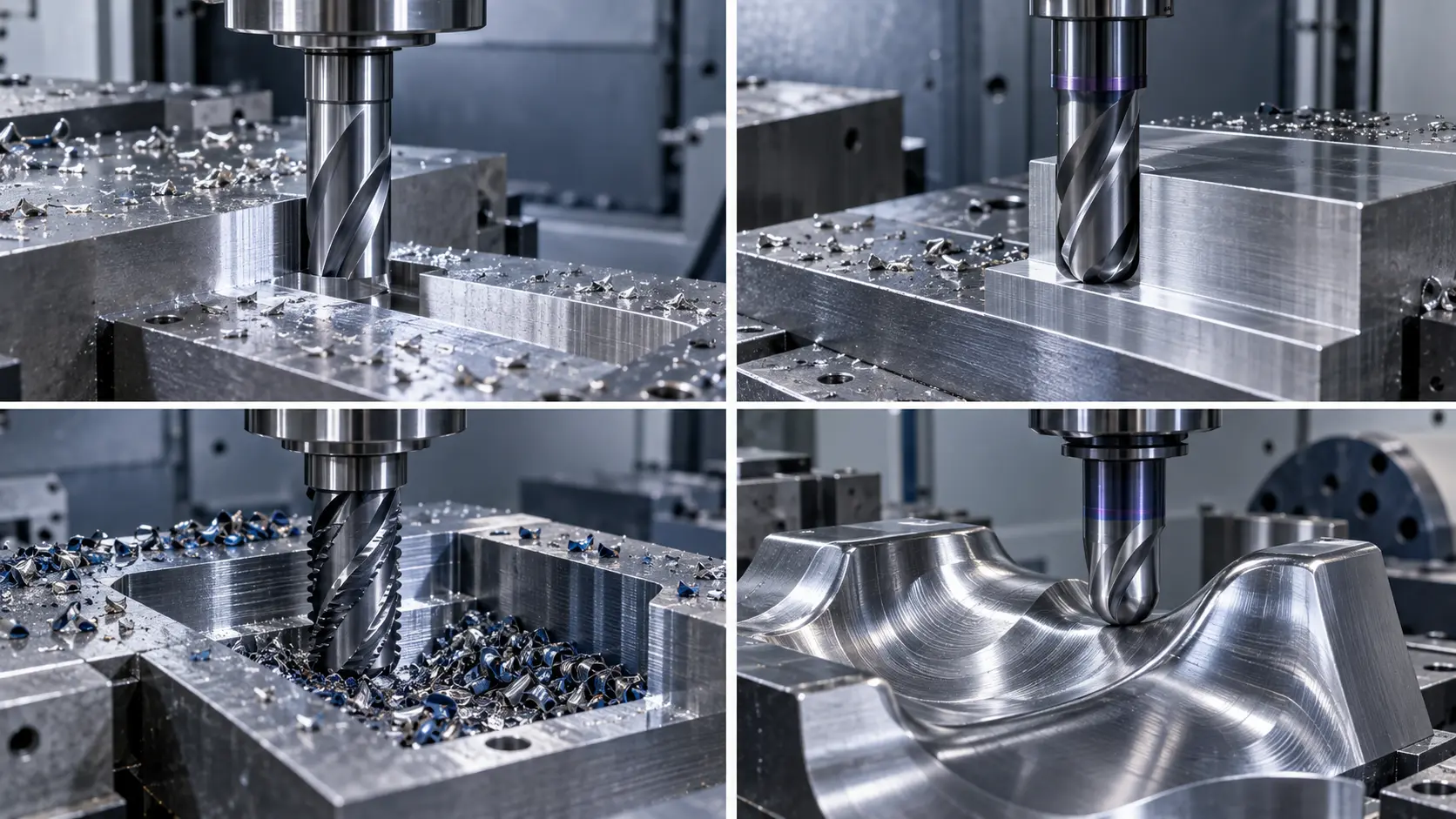
Slotting and Pocketing
For a full-width slot, start with the required slot width and depth, then check the tool’s cutting length, flute space, entry design, and chip-removal plan. A square end mill is a common starting profile for a flat-bottom slot, but the exact flute count and geometry depend on the material and engagement.
Pocketing may combine multiple operations: roughing, clearing corners, semi-finishing, and finishing. One tool may not be the most suitable choice for all stages. If the pocket is deep, consider whether the holder can reach without collision and whether the chosen cutting length leaves unnecessary unsupported tool length.
Side and Shoulder Milling
Side milling creates a wall or profile; shoulder milling may create a wall and adjacent floor in one operation. A square tool can produce a flat floor and defined corner, while a corner radius tool is an option when the drawing permits a radius and the process needs that profile.
Review radial engagement, axial depth, wall tolerance, corner geometry, and tool overhang. If the wall tapers or the finish changes along the cut, review setup rigidity and runout as well as the cutter. The tool should be selected from the part geometry, not from an assumed preference for one profile.
Mold Contouring and 3D Finishing
A ball nose end mill is commonly considered for continuously changing 3D surfaces. A corner radius end mill may suit a shallower profile or a surface with a flat floor and an allowed corner radius. A square end mill may suit a flat floor or straight wall that requires a sharper transition.
Check the smallest concave radius, tool access, surface curvature, and finish allowance. Tool diameter and stepover influence how the cutter follows the surface. For mold work, the operation may use more than one geometry: a larger tool for accessible stock removal and a smaller or different-profile tool for the remaining detail. Confirm the actual toolpath and stock allowance before changing cutter types.
Deep Cavities and Micro Features
Start with the shortest standard cutter that can reach the accessible part of the feature. Move to a long-neck or extended-reach design only when clearance requires it. For a micro feature, consider a smaller cutter only after checking runout, holder accuracy, entry method, chip evacuation, and the available machine stability.
These constraints are not solved by selecting a longer or smaller tool alone. The toolpath may need to reduce engagement, avoid sudden direction changes, or machine the feature in stages. Verify the proposed method with the CAM program and tool data.
End Mill Dimensions: What to Check Before You Choose
End mill dimensions determine whether a cutter can reach the feature, clear the workpiece, and remain stable in the holder. Check the drawing and distinguish the cutting portion from the shank and overall tool length before ordering.
- Cutting diameter: Match the nominal diameter and tolerance to slot width, profile geometry, and required clearance.
- Flute length: Specify the axial cutting length needed to machine the feature; avoid excess length that reduces rigidity.
- Neck length and neck diameter: Use these dimensions to verify clearance in deep pockets and recessed areas without confusing clearance with cutting length.
- Shank diameter: Confirm compatibility with the collet or toolholder and its clamping range.
- Overall length: Check the assembled reach and possible interference with the spindle, holder, fixture, and workpiece.
For a custom or long-reach cutter, provide a dimensioned drawing and identify which lengths are critical. Confirm the tool series, tolerance, and measurement reference with the supplier. See our carbide end mills for standard options.
Which end mill dimensions are most important?
Start with cutting diameter, flute length, neck clearance, shank diameter, and overall length. The critical dimensions depend on the feature, holder, and machine setup, so confirm them against the drawing and tool assembly.
What is the difference between flute length and overall length?
Flute length is the cutting-edge length along the tool, while overall length measures the cutter from end to end. A long overall tool may still have a short cutting section; specify cutting length and clearance separately.
A Practical End Mill Selection Workflow
Use the following sequence before selecting or requesting a quote:
- Describe the feature. Is it a flat floor, sharp inside corner, curved surface, shoulder, deep wall, undercut, thread, or small detail?
- Identify the operation. Define slotting, side milling, roughing, finishing, contouring, or another programmed cut.
- Choose the end profile. Select square, ball nose, corner radius, chamfer, tapered, or a specialty cutter according to the required geometry.
- Check access. Confirm tool diameter, cutting length, neck clearance, overall length, holder, and fixture interference.
- Check the process conditions. Include material and hardness, machine, holder, overhang, coolant or air, toolpath, and engagement.
- Define the quality target. State the required dimensions, surface finish, edge condition, and whether the tool is for a prototype or repeat production.
- Confirm with the exact tool data. Ask the supplier to identify the product series and the assumptions behind its recommendation. Trial the tool in a controlled process before standardizing it.
This sequence avoids requesting a tool by diameter alone. Equal-diameter cutters may differ in profile, flute geometry, length, neck, edge preparation, and intended application.
Common End Mill Selection Mistakes
- Choosing only by nominal diameter. The tool may fit the slot width but still have the wrong profile, reach, or cutting length.
- Treating every “type” as a separate shape. A long-neck ball nose combines an access design and an end shape; roughing describes a purpose.
- Ignoring the part’s internal radius. A corner radius cutter cannot create a smaller inside corner than its own cutting radius.
- Adding unnecessary reach. Extra tool length can increase deflection and vibration.
- Assuming center cutting means any plunge is safe. Axial entry still depends on the tool design, material, depth, and chip evacuation.
- Using one tool for every machining stage. Roughing and finishing may have different priorities for stock removal, accuracy, and surface quality.
- Blaming the cutter before checking the setup. Runout, workholding, toolpath, and chip evacuation can cause instability even when the end profile is suitable.
- Copying conditions from a similar-looking tool. Confirm the manufacturer’s data for the exact series and setup.
What to Send a Supplier for an End Mill Recommendation
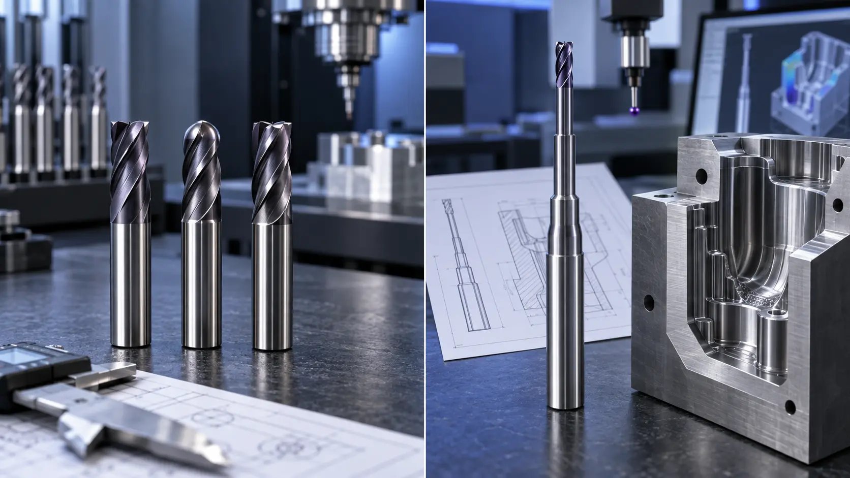
A clear inquiry helps a supplier distinguish a standard tool request from a geometry or access problem. Include:
- Workpiece material, grade, and hardness
- Part or tool drawing, with the feature and internal radii identified
- Operation and machining stage
- Required cutting diameter and tolerance
- Cutting length, neck length, shank diameter, and overall length
- End profile, corner radius, taper angle, or specialty feature
- Machine, spindle, holder, tool overhang, and coolant conditions
- Toolpath type, engagement, and the current issue if replacing a tool
- Quantity, packaging, branding, or other customization requirements
For customization, identify critical dimensions and sample-approval steps. Confirm the final specification in writing and define trial acceptance criteria. A custom tool may address geometry or access needs, but does not replace a setup review.
Frequently Asked Questions
What are the main types of end mills?
Common types include square, ball nose, corner radius, chamfer, tapered, roughing, finishing, long-neck, and micro end mills. Specialty milling cutters include thread mills, T-slot cutters, dovetail cutters, and lollipop tools. The names describe different design dimensions, so one cutter may fit more than one category.
What is the difference between square, ball nose, and corner radius end mills?
A square end mill has a flat end and defined corner for features such as slots and flat floors. A ball nose end mill has a rounded end for curved surfaces and 3D contours. A corner radius end mill has a flat area with a specified radius at the corner, useful when the part allows that geometry.
Which end mill type is used for flat surfaces?
A square or flat end mill is a common choice for flat floors, slots, pockets, and straight walls. The suitable tool depends on the feature width, corner requirement, access, material, and machining setup.
Which end mill works for 3D contouring?
A ball nose end mill is commonly selected for continuously changing 3D surfaces, mold cavities, and freeform contours. Confirm the smallest surface radius, tool access, stepover, and finish requirement before selecting the ball diameter.
When should you use a roughing end mill?
Consider a roughing end mill when stock removal and chip control are the priority and a later finishing pass is planned. Check that the roughing geometry, engagement, machine, and remaining stock allowance fit the operation.
What is a long-neck end mill used for?
A long-neck or reduced-neck end mill provides clearance for a deep or recessed feature when the holder or shank might otherwise interfere. Use only the reach required and confirm that the cutting length and assembled overhang are suitable for the setup.
Are thread mills and T-slot cutters types of end mills?
They are specialty milling cutters used on CNC machines, but they are designed for specific features. Thread mills create threads through a programmed path; T-slot cutters create an undercut slot after access is prepared. Confirm the tool geometry and programming requirements for the exact feature.
What information should you send when requesting an end mill recommendation?
Send the workpiece material and hardness, drawing or feature dimensions, operation, tool diameter and reach, end profile, machine and holder details, coolant conditions, quality target, and quantity. Include a photo only as supporting context; dimensions and drawings are more useful for a precise recommendation.
Conclusion
End mill types solve different geometry, machining-stage, and access problems. Start with the drawing, then check profile, reach, flute space, toolpath, and machine conditions. Confirm specialty-tool specifications before ordering.
If a standard cutter does not match the required profile, corner, or reach, prepare the drawing and machining details for a supplier review. Review ZIROO TOOLS standard carbide end mills and contact ZIROO TOOLS for a tooling review. Confirm the current product specification and commercial terms for the exact requirement before qualification.