What Size Drill Bit for a 5/16 Tap? Complete Size Guide
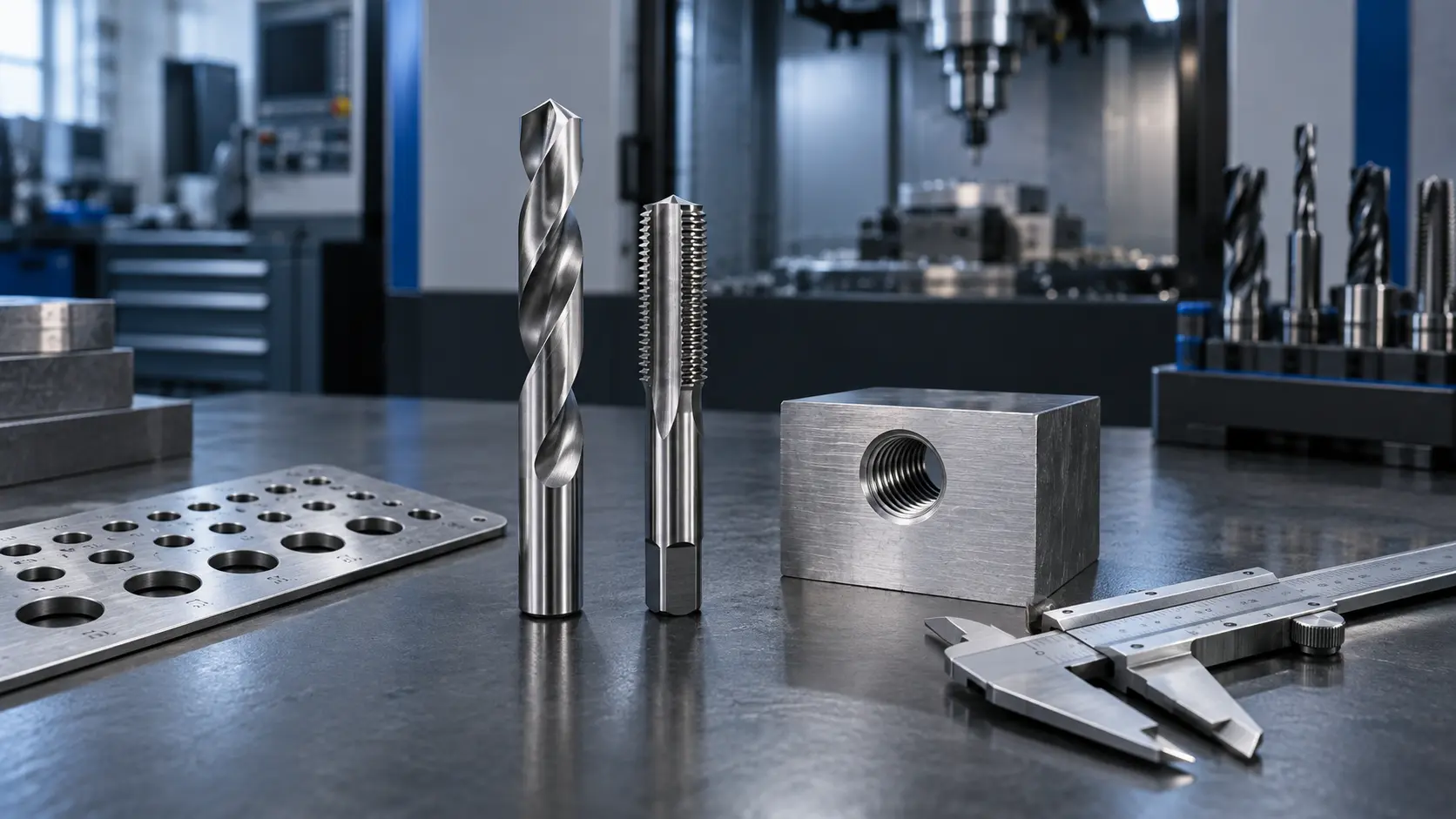
What size drill bit should you use for a 5/16 tap? For a standard cutting tap, the usual answer is a Letter F drill (0.2570 inch or 6.53 mm) for a 5/16-18 UNC thread and a Letter I drill (0.2720 inch or 6.91 mm) for a 5/16-24 UNF thread. A 5/16-32 UNEF tap commonly uses a 9/32-inch drill.
However, “5/16” alone is not enough information to select a drill. You must also confirm the thread pitch, workpiece material, required thread engagement, hole type and whether you are using a cutting or forming tap. These factors affect tapping torque, thread quality and tool life.
This guide explains the standard sizes, practical substitutes and production checks needed to create reliable 5/16-inch internal threads. The main size table applies to conventional cutting taps. Always use the tap manufacturer’s recommended hole size when working with a forming tap or a critical threaded joint.
Quick Answer: 5/16 Tap Drill Size Chart
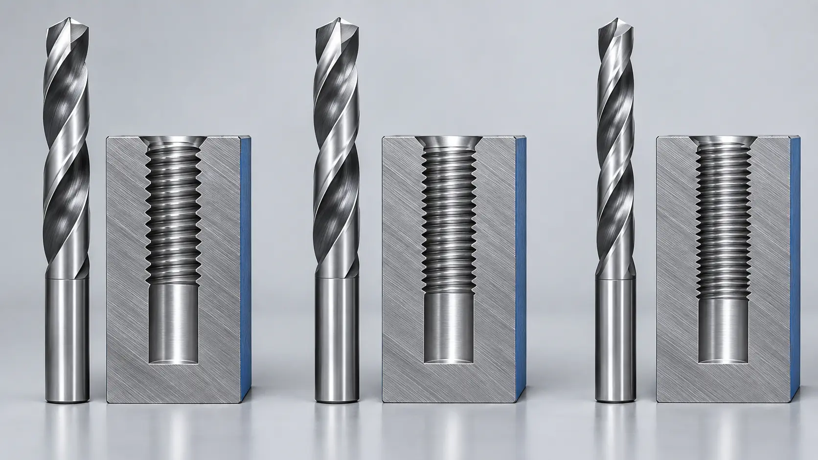
| Tap size | Thread series | Standard drill | Decimal size | Metric equivalent | Closest common fractional size |
|---|---|---|---|---|---|
| 5/16-18 | UNC | Letter F | 0.2570 in | 6.53 mm | 17/64 in (larger than F) |
| 5/16-24 | UNF | Letter I | 0.2720 in | 6.91 mm | No exact common fractional equivalent |
| 5/16-32 | UNEF | 9/32 in | 0.28125 in | 7.14 mm | 9/32 in |
These are reference sizes for cut threads. The actual hole produced may be larger or smaller than the drill’s nominal diameter because of runout, tool wear, machine condition and workpiece behavior. In production, measure the finished hole rather than relying only on the marking on the drill shank. For another numbered-thread example, see the ZIROOTOOLS guide to the 10-32 tap drill size.
Why Does a 5/16 Tap Have Different Drill Sizes?
What “5/16” Means
The first part of a Unified thread designation identifies its nominal major diameter. A 5/16-inch thread has a nominal outside diameter of 0.3125 inch. This number does not describe the distance between the threads, so it cannot determine the tap drill size by itself.
A complete callout includes the number of threads per inch. For example, 5/16-18 means a nominal 5/16-inch diameter with 18 threads per inch. A 5/16-24 thread has 24 threads per inch. Always check the tap marking, engineering drawing or fastener specification before drilling.
What 18, 24 and 32 TPI Mean
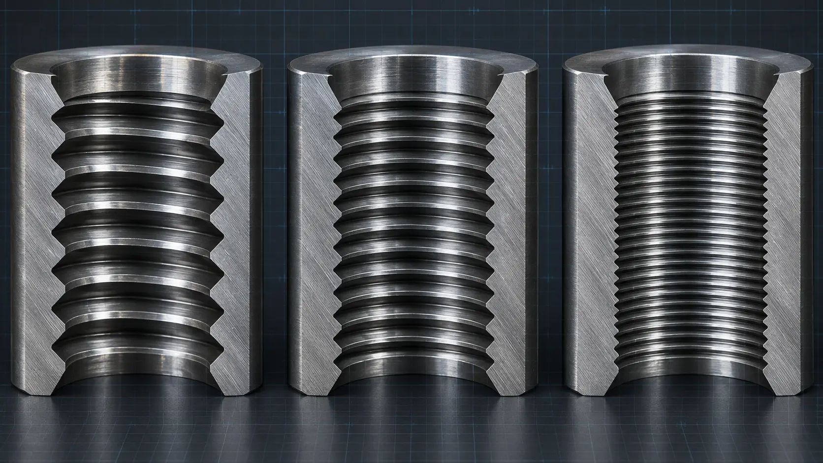
TPI means threads per inch. A lower TPI creates a coarser pitch with deeper, more widely spaced threads. A higher TPI creates finer, shallower threads. Because the thread profiles remove different amounts of material, each pitch requires a different pre-drilled hole.
- 5/16-18 UNC: a common coarse thread for general fastening.
- 5/16-24 UNF: a common fine thread used where finer adjustment, more threads in a limited engagement length or a different fastening design is required.
- 5/16-32 UNEF: an extra-fine thread used in more specialized applications.
Do not select the pitch based only on which tap is available. The mating fastener, drawing and functional requirements must use the same thread series.
5/16-18 Tap Drill Size
Standard Letter F Drill
The standard reference drill for a 5/16-18 UNC cutting tap is a Letter F drill. Its nominal diameter is 0.2570 inch, or approximately 6.53 mm. This size is commonly associated with a conventional thread percentage close to that used in standard tap drill charts.
For a controlled machining process, verify both the drill diameter and the hole it produces. A drill can cut oversize because of spindle or holder runout, unequal cutting lips, poor point geometry or unstable fixturing. It can also produce inconsistent holes as the cutting edge wears.
Can You Use a 17/64-Inch Drill Instead?
A 17/64-inch drill measures 0.265625 inch. It is approximately 0.0086 inch larger than a Letter F drill, so the two sizes are not identical. The larger hole generally reduces the amount of material the tap must remove and may reduce tapping torque, but it also produces a lower thread percentage.
Whether 17/64 inch is acceptable depends on the joint requirement, material, tap geometry and inspection criteria. It may be a practical alternative in a noncritical application after testing, but it should not automatically replace Letter F on a controlled drawing. For a production part, calculate the target engagement and approve the resulting thread through first-piece inspection.
Why a 1/4-Inch Drill Is Usually Too Small
A 1/4-inch drill is 0.2500 inch, which is smaller than Letter F. The smaller hole leaves more material for the tap to remove. That can raise torque, make chip evacuation more difficult and increase the risk of tap chipping or breakage.
Using a smaller hole does not automatically create a better or stronger connection. Beyond a practical thread engagement range, the additional cutting load may be substantial while the improvement in joint performance is limited. Use the specified drill size unless the threading process has been engineered and validated for a different hole.
5/16-24 Tap Drill Size
Standard Letter I Drill
The common drill for a 5/16-24 UNF cutting tap is a Letter I drill. It has a nominal diameter of 0.2720 inch, or approximately 6.91 mm. Because this is a fine thread, it uses a larger pilot hole than the coarse 5/16-18 thread.
Do not confuse Letter I with the number 1 or assume that a 5/16-18 drill will work simply because the nominal thread diameter is the same. The thread pitch changes the required hole diameter.
Why Fine Threads Need a Larger Pilot Hole
A fine thread has a smaller pitch and shallower thread depth. The hole therefore begins closer to the final minor diameter of the internal thread. This is why the Letter I drill for 5/16-24 is larger than the Letter F drill used for 5/16-18.
The larger hole does not mean the fine thread is defective or inherently loose. It reflects the geometry of the specified thread form. Thread performance also depends on engagement length, material, tolerances and the mating fastener.
Can You Use 17/64 Inch for a 5/16-24 Tap?
A 17/64-inch drill measures about 0.2656 inch, which is smaller than the 0.2720-inch Letter I drill. It will create a higher thread percentage and typically require more tapping torque. For this reason, 17/64 inch should not be presented as the default substitute for a 5/16-24 tap.
If the exact letter drill is unavailable, choose an alternative through calculation and testing rather than convenience alone. For critical components, use the drill size and tolerance specified by the tap manufacturer or engineering drawing.
What About a 5/16-32 Tap?
A 5/16-32 UNEF cutting tap commonly uses a 9/32-inch drill, measuring 0.28125 inch or about 7.14 mm. This extra-fine series is less common than 5/16-18 and 5/16-24, so verify the exact callout before ordering a drill or programming the operation.
Extra-fine threads may be selected for specialized adjustment, thin-wall or application-specific requirements, but suitability must be determined by the component designer. Do not substitute 5/16-32 for another 5/16 thread series because the mating parts will not be compatible.
Check the Arithmetic Before Choosing the Nearest Drill
A useful shop approximation for a Unified cutting-tap hole is:
Tap drill diameter ≈ nominal major diameter − (1 ÷ threads per inch)
For 5/16-18, the calculation is 0.3125 − (1 ÷ 18) = 0.2569 inch, which is extremely close to the 0.2570-inch Letter F drill. For 5/16-24, the calculation gives 0.2708 inch; the standard Letter I drill is 0.2720 inch. For 5/16-32, the result is 0.28125 inch, exactly 9/32 inch.
This approximation helps explain the chart, but it does not define every production hole. It does not account for thread class, tap-specific geometry, forming taps, material response or the actual diameter cut by the drill. Use it as a reasonableness check before selecting the nearest available drill—not as permission to ignore the drawing or tool supplier’s data. The same tap-type-first decision process is explained in the related 1/4-20 tap drill size guide.
How Tap Drill Size Relates to Thread Percentage
What Is Thread Percentage?
Thread percentage is a practical way to describe how much of the theoretical internal thread height is formed. A smaller tap drill produces a higher percentage because more material remains for the tap to cut. A larger drill produces a lower percentage and reduces the cutting load.
Higher thread percentage is not automatically better. As the percentage rises, tapping torque can increase quickly. The process may become less stable, especially in difficult materials, deep holes or small-diameter threads.
Why Many Charts Use About 75%
Many traditional tap drill charts provide a size associated with approximately 75% thread. This creates a useful reference point for common applications, but it is not a universal requirement for every material or joint. Guhring’s tap drill calculator and thread-percentage guidance explains why useful drill-size ranges can vary with the application.
The final decision should consider the required load, engagement length, material strength, tap design and production stability. If the part is safety-critical or governed by a drawing, standard or customer specification, those requirements take priority over a general-purpose chart.
When a Lower Thread Percentage May Help
A lower percentage may reduce tapping torque and improve process reliability. It can be worth evaluating when:
- the tap is breaking or chipping despite correct alignment;
- the workpiece material produces high cutting forces;
- the thread is deep and chip evacuation is difficult;
- tool life varies significantly across a production batch;
- the machine or holder shows high tapping load; or
- the specified engagement length already provides sufficient functional strength.
Any change must remain within the permitted internal-thread dimensions. Validate it with the appropriate inspection method rather than changing the drill size solely to make tapping easier.
Before Applying the Chart, Confirm How the Tap Makes the Thread
Cutting Taps
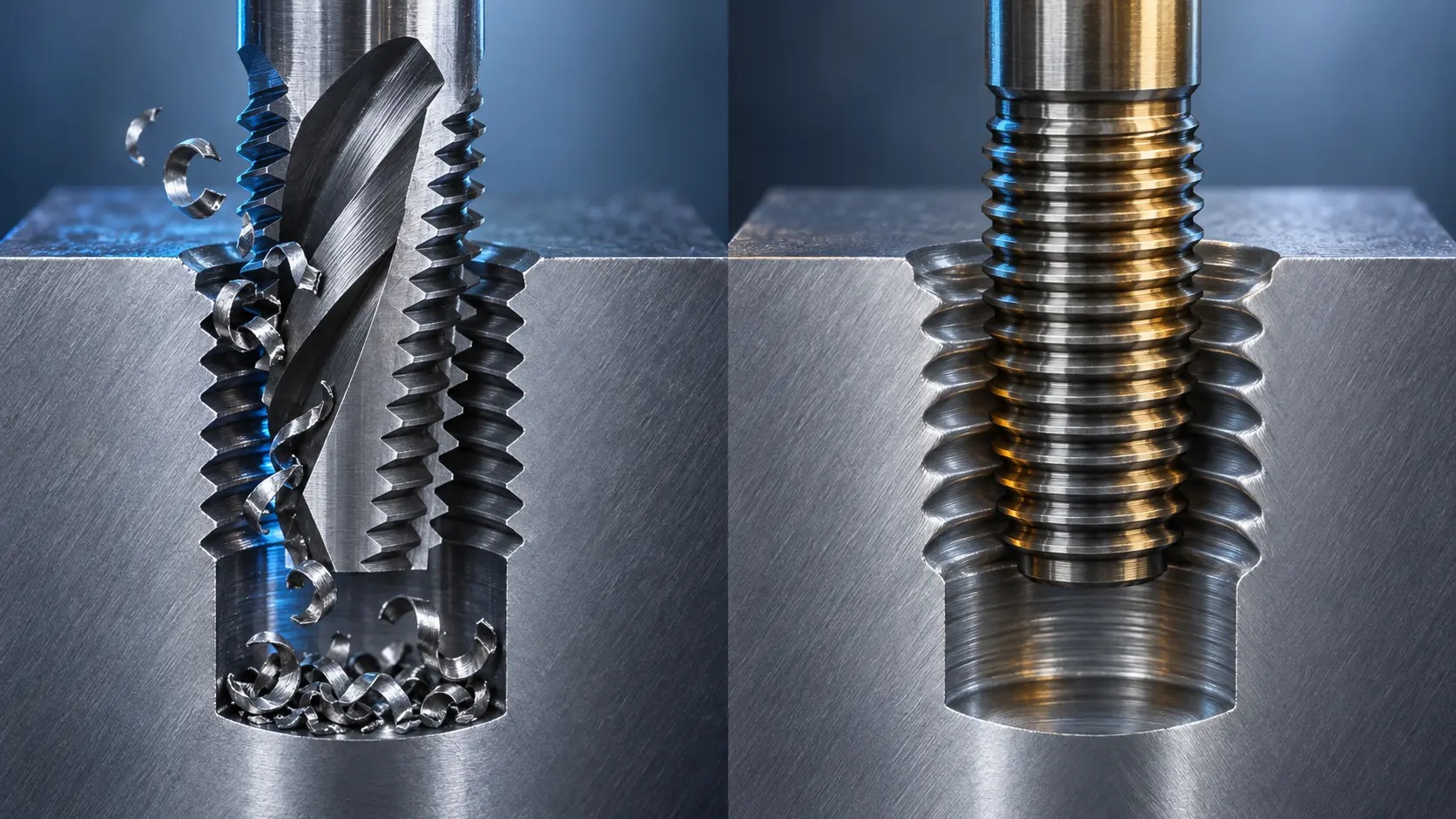
A cutting tap removes material to create the internal thread. Its flutes provide cutting edges and space for chips. The Letter F, Letter I and 9/32-inch recommendations in this guide are reference values for conventional cut threads.
Chip direction matters. Spiral-point taps are commonly used to push chips ahead in suitable through-hole applications, while spiral-flute taps are often selected to lift chips out of blind holes. The correct selection depends on material, hole geometry and machine conditions.
Forming Taps
A forming or roll tap displaces ductile material instead of cutting it away. It does not create chips in the same way, but it requires a carefully controlled pre-hole. A hole intended for a cutting tap is generally too small for the equivalent forming tap.
Using the wrong pre-hole can cause excessive torque, poor thread formation or tool failure. Always follow the forming-tap manufacturer’s chart for the exact tap, material and desired thread condition. Do not use this article’s cutting-tap table as a forming-tap specification.
Material Behavior Can Change the Hole You Actually Produce
Mild Steel
Mild steel is commonly tapped, but the process still depends on stable alignment, suitable lubrication and reliable chip evacuation. Monitor the actual hole diameter and tap condition during a long batch. Worn drills can change the pre-hole and transfer additional load to the tap.
Stainless Steel
Stainless steel can generate heat and may work-harden when the tool rubs instead of cutting. A rigid setup, sharp tools, suitable cutting conditions and consistent feed are important. Avoid selecting a smaller hole simply to maximize thread percentage because the additional torque may reduce process reliability.
Aluminum
Aluminum is easier to cut than many steels, but some alloys can adhere to cutting edges and affect the finished hole. Tool geometry, lubrication and chip control still matter. Measure the hole after drilling because built-up material or runout can change the result.
Plastics and Other Nonferrous Materials
Plastics may deflect, heat up or recover after drilling. Some nonferrous alloys also produce long or adhesive chips. The same nominal drill can therefore create different actual holes in different materials. Test the complete drilling and tapping process on representative material before approving production.
Through Hole vs Blind Hole
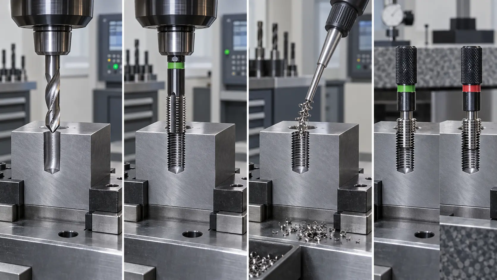
Through Holes
A through hole allows the drill and, in suitable operations, chips to pass through the workpiece. It usually simplifies depth planning, but you still need to consider breakthrough burrs, fixture clearance and the required full-thread length.
Where a spiral-point tap pushes chips forward, make sure there is enough clearance below the part. Chips trapped between the workpiece and fixture can damage the part or affect seating.
Blind Holes
A blind hole stops inside the workpiece. Its drilled depth must be greater than the required full-thread depth. The additional depth is not one universal value; it must account for:
- the drill-point length;
- the tap’s chamfer or lead;
- the required full-form thread depth;
- chip accumulation or evacuation space; and
- a safe clearance that prevents the tap from contacting the bottom.
Start with the component drawing and the geometry of the selected drill and tap. If threads must extend close to the bottom, the process may require a plug or bottoming tap after the initial operation. Verify that the part has enough remaining wall thickness before increasing the drilled depth.
Build a Controlled 5/16 Drilling and Tapping Process
- Confirm the complete thread callout. Identify whether the requirement is 5/16-18, 5/16-24 or 5/16-32. Confirm the class, depth and mating fastener where applicable.
- Identify the tap type. Determine whether the process uses a cutting tap or forming tap. Do not apply a cut-tap drill chart to a forming tap.
- Review the workpiece material. Consider hardness, ductility, tendency to work-harden and chip behavior.
- Select the target pre-hole. Begin with the specified standard or manufacturer recommendation, then account for the approved thread percentage and tolerance.
- Inspect the drill and setup. Check tool diameter, edge condition, runout, holder condition and workpiece clamping.
- Drill the hole. Use cutting conditions and coolant or lubricant appropriate to the drill and material. Maintain alignment and clear chips as required.
- Measure the finished hole. Use a suitable bore-measuring method. Do not assume the hole matches the nominal drill diameter.
- Chamfer and remove burrs. A controlled entry chamfer can help the tap start, but excessive chamfering reduces usable thread length.
- Tap the hole. Maintain alignment, use the correct lubrication strategy and control chip flow. Hand tapping and machine tapping require different operating practices.
- Inspect the thread. Use the specified GO/NO-GO thread plug gauge for controlled production. A mating bolt can provide a basic functional check but is not a substitute for required gauging.
Common Problems and Corrective Actions
| Problem | Likely cause | Corrective action |
|---|---|---|
| Tap breaks or chips | Hole too small, misalignment, chip packing, worn tap or excessive torque | Measure the hole, check alignment and review the tap, lubricant and chip-control method |
| Tapping torque is too high | Excessive thread percentage, poor lubrication or unsuitable cutting conditions | Verify pre-hole size and review the approved process parameters |
| Thread feels loose | Oversized hole, drill runout, incorrect tap or worn tooling | Measure the drilled hole and inspect the thread with the specified gauge |
| Incomplete thread near the bottom | Insufficient drilled depth or tap chamfer not included in the calculation | Recalculate drill-point, tap-lead and chip-clearance allowances |
| Tool life varies between batches | Material variation, changing hole size, unstable runout or inconsistent lubrication | Record actual hole size and tapping load, then establish a controlled replacement limit |
| GO gauge will not enter | Undersized thread, damaged form, chips or incorrect pitch | Clean the hole, confirm the callout and inspect the drilling and tapping operations |
Release the Process, Not Just the First Good Part
First-Piece Inspection
Before releasing a production batch, inspect the full operation rather than checking only the finished thread. A practical first-piece record should include:
- drill identification and measured diameter;
- tool runout at an appropriate location;
- finished pre-hole diameter and depth;
- entry chamfer condition;
- effective full-thread depth;
- GO and NO-GO gauge results; and
- visible burrs, tearing or chip damage.
If the machine provides spindle-load or tapping-torque information, record the normal first-piece range. A rising load can help identify tool wear, chip buildup or a change in the drilled hole before a tap fails.
Batch Monitoring
For repeat production, define checks based on process risk. Monitor the drilled-hole size, gauge result and tool condition at planned intervals. Do not wait for a broken tap to establish the replacement point.
When changing drill suppliers, tool geometry, coating, coolant, workpiece material lot or machine, repeat the appropriate validation. Two drills with the same nominal diameter may not produce identical results under the same program.
When Should You Use a Standard or Custom Drill?
A Standard Tool Is Usually Enough When
- the part uses a standard 5/16 thread and a simple straight hole;
- the depth-to-diameter ratio is moderate;
- the machine and holder provide adequate rigidity;
- the required drill size is readily available; and
- the cycle does not require several related features to be combined.
Consider a Custom Carbide Drill When
A custom tool may be worth evaluating when the component requires a stepped pilot hole, integrated chamfer, special reach, controlled drill point or a combination of operations. It may also help when tool changes limit cycle time or when a standard geometry does not provide stable results in the target material. Review the ZIROOTOOLS OEM and custom cutting-tool service when a standard drill cannot combine the required features.
The decision should be based on the complete operation, not the thread size alone. ZIROOTOOLS can review the drawing, workpiece material, hole depth, batch quantity, machine, holder and coolant conditions to assess whether a standard drill or a custom carbide solution is more appropriate. Any final recommendation should be validated on the actual production setup.
5/16 Tap Drill Selection Checklist
- Confirm whether the thread is 5/16-18, 5/16-24 or 5/16-32.
- Confirm the thread class, required engagement and full-thread depth.
- Identify whether the process uses a cutting or forming tap.
- Review the workpiece material and chip behavior.
- Select the target thread percentage and approved pre-hole tolerance.
- Verify the drill’s actual diameter, condition and runout.
- Calculate additional depth for blind-hole geometry and chip clearance.
- Measure the finished hole before tapping the first production part.
- Inspect the completed thread with the required gauge.
- Record the result and establish an in-process inspection interval.
Conclusion
For a conventional cutting tap, use a Letter F drill for 5/16-18 UNC and a Letter I drill for 5/16-24 UNF. A 5/16-32 UNEF thread commonly uses a 9/32-inch drill. A 17/64-inch drill is larger than Letter F and may be a practical alternative for some 5/16-18 applications, but it is not an exact replacement.
Before machining, confirm the pitch and tap type. Then account for the material, target thread percentage, through-hole or blind-hole geometry and actual hole produced by the drill. Measuring the pre-hole and inspecting the finished thread are more reliable than choosing a tool by nominal size alone.
If your project involves a stepped hole, unusual reach, difficult material or high-volume production, send ZIROOTOOLS your drawing and machining conditions. The engineering review can compare a standard drilling process with a purpose-designed carbide tool before you commit to production.
Technical References
- Lincoln Machine tap drill chart — standard 5/16-18, 5/16-24 and 5/16-32 reference sizes.
- Guhring tap drill calculator — thread-percentage and tap-drill selection guidance.
- Machining Doctor 5/16-18 UNC data — thread dimensions and percentage-based drill sizes.
- Machining Doctor 5/16-24 UNF data — fine-thread dimensions and drill-size ranges.
Frequently Asked Questions
What size drill bit do I need for a 5/16-18 tap?
Use a Letter F drill for a standard 5/16-18 UNC cutting tap. Letter F measures 0.2570 inch, or approximately 6.53 mm. A 17/64-inch drill is a larger fractional alternative, but it produces a lower thread percentage and should be validated for the application.
What size drill bit do I need for a 5/16-24 tap?
Use a Letter I drill for a standard 5/16-24 UNF cutting tap. It measures 0.2720 inch, or approximately 6.91 mm. Confirm the recommendation supplied with the tap for critical or production applications.
Can I use a 17/64-inch drill for a 5/16-18 tap?
It may be acceptable in some applications, but it is not identical to Letter F. A 17/64-inch drill is about 0.0086 inch larger, reducing thread engagement and tapping torque. Test and inspect the resulting thread before approving it for production.
Can I use a 1/4-inch drill bit for a 5/16 tap?
A 1/4-inch hole is smaller than the standard Letter F hole for 5/16-18 and much smaller than Letter I for 5/16-24. It can create excessive tapping torque and a higher risk of tool failure. It should not be used as the default size.
What is the metric equivalent of a Letter F drill?
Letter F measures 0.2570 inch, equal to approximately 6.53 mm. A 6.5 mm drill is close but not exact. Use the permitted hole tolerance and measure the actual drilled hole before accepting a metric substitute.
Why does a 5/16-24 tap use a larger drill than a 5/16-18 tap?
The 24-TPI thread has a finer pitch and shallower thread form than the 18-TPI thread. Its required internal-thread minor diameter is therefore larger, so it uses a larger pre-drilled hole.
How deep should I drill for a blind 5/16 tapped hole?
Drill deeper than the required full-thread depth by an amount that accounts for the drill point, tap chamfer, chip space and safe bottom clearance. There is no single extra-depth value for every tool. Calculate it from the selected drill, tap and part geometry.
Does a forming tap use the same drill size as a cutting tap?
No. A forming tap displaces material and normally requires a larger, more tightly controlled pre-hole than a cutting tap. Use the forming-tap manufacturer’s recommended drill size for the exact material and thread requirement.