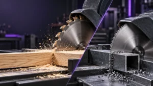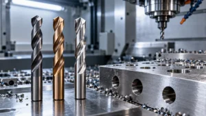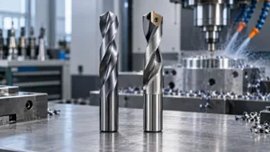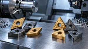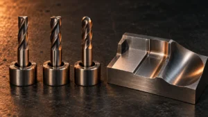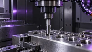
Milling cutter tools remove material with multiple cutting edges on a milling machine or machining center. But “milling cutter” is a broad term: a tool that produces a flat reference surface is not automatically suitable for a deep slot, a 3D mold contour, a composite panel, or a tiny medical part. The correct choice depends on the workpiece material, machining operation, required accuracy, machine rigidity, holder system, and production target.
This guide explains the main types of milling cutter tools, the materials and structures available, and a practical selection method for manufacturers, distributors, and OEM buyers. It also covers common machining problems and the information ZIROO TOOLS needs to evaluate a standard or custom milling-tool project.
What Are Milling Cutter Tools?
Milling cutters are rotary cutting tools used to create flats, pockets, slots, profiles, holes, threads, chamfers, and complex three-dimensional surfaces. Cutting edges may be located on the tool end, the outside diameter, the face, or a specially formed profile. They are used on manual milling machines, CNC machining centers, gantry machines, routers, and dedicated production equipment.
Unlike a single-point turning tool, a milling cutter repeatedly enters and leaves the workpiece. This interrupted cut creates changing forces and heat. Tool geometry, flute count, helix angle, coating, overhang, coolant delivery, and workholding all influence tool life and surface finish.
Quick Guide to Milling Cutter Types
| Tool type | Typical use | Key selection point |
|---|---|---|
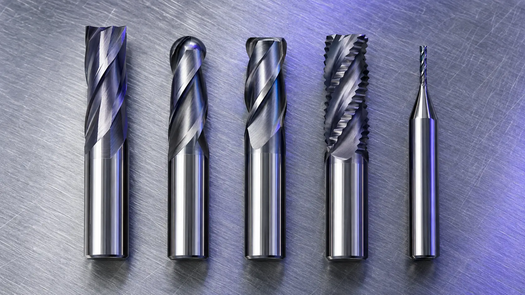
| Square end mill | Slots, pockets, side milling, 90° shoulders | Choose flute count and corner design for material and chip evacuation |
| Ball nose end mill | 3D surfaces, mold finishing, radiused profiles | Use a suitable step-over and rigid holder to control scallop height |
| Corner-radius end mill | Shoulders, pockets, semi-finishing, mold work | Corner radius improves edge strength compared with a sharp corner |
| Roughing end mill | High-volume stock removal | Match chip-breaker design and flute count to available power and chip flow |
| Face mill | Large flat surfaces and datum creation | Diameter, insert geometry, runout, and cutter-body rigidity are critical |
| Slotting or T-slot cutter | Slots, keyways, T-slots | Confirm neck clearance, slot dimensions, and chip evacuation path |
| Thread mill | Internal or external threads | Confirm thread standard, pitch, depth, material, and machine interpolation capability |
| Form, dovetail, and lollipop cutter | Undercuts and special profiles | Start from the finished profile drawing and access geometry |
| Micro end mill | Electronics, medical parts, small molds | Minimize runout and overhang; micro tools are highly sensitive to setup |
Main Types of Milling Cutter Tools
End Mills
End mills cut with both their end and peripheral edges. Square end mills create flat-bottom pockets, slots, and vertical walls. Ball nose end mills are used for blended radii and 3D contours. Corner-radius end mills retain a small radius at the corner to strengthen the edge and reduce chipping in demanding operations.
For a detailed comparison of end-mill geometries, see our guide to matching end mill types to CNC machining needs. When buying standard or custom end mills, specify diameter, flute length, overall length, shank diameter, corner condition, coating, material, and the workpiece material rather than requesting only a “carbide end mill.”
Face Mills
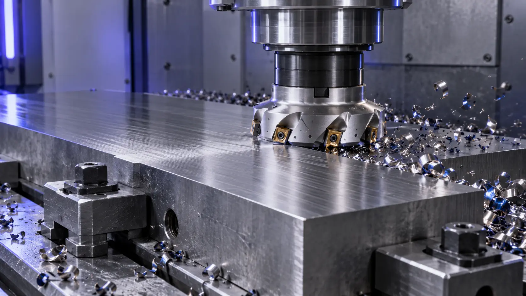
Face mills produce broad flat surfaces with one or more inserts or cutting edges positioned on the cutter face. They are commonly used to establish datum surfaces before finishing features, and to machine large areas efficiently. The best face-milling result comes from a complete system: cutter diameter, insert grade and geometry, holder, spindle condition, workholding, and programmed engagement must work together.
Slotting Cutters
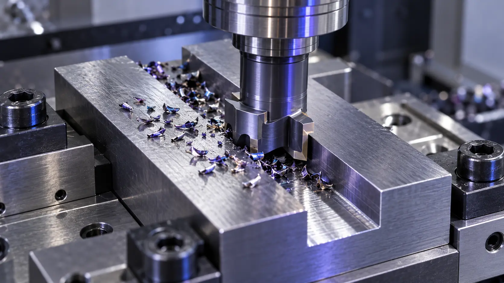
Slotting includes end-milling slots, side-and-face milling, slitting, keyway cutting, and T-slot machining. Full-width engagement increases chip load and can trap heat, so tool diameter, flute design, coolant strategy, and the available chip-exit path require special attention. A T-slot cutter is normally used after a straight slot has already been machined for neck clearance.
Thread Mills
Thread mills generate threads by circular interpolation rather than driving a tap directly into the hole. They can be useful where a single tool must cover several diameters with the same pitch, where blind-hole chip control is difficult, or where the workpiece material makes tapping less predictable. The machine must support the correct interpolation program, and the tool must match the thread form, pitch, depth, and handedness.
Form and Undercut Cutters
Form cutters produce a specified profile, such as a radius, dovetail, chamfer, or custom contour. Lollipop and undercut end mills reach areas that a standard end mill cannot access. These tools should be chosen from the finished part drawing, especially the smallest opening, clearance angle, radius, and required surface condition. For complex profiles, a drawing or 3D model allows a supplier to review whether a standard tool is sufficient or a custom profile is needed.
Micro Milling Cutters
Micro end mills are used for small cavities, fine features, PCB-related components, precision molds, and medical-device parts. At small diameters, spindle runout and unnecessary overhang can consume a large share of the available edge strength. Use accurate holders, clean collets or shrink-fit systems, short projection, stable workholding, and conservative process development.
Milling Cutter Materials and Structures
HSS Milling Cutters
High-speed steel cutters offer toughness and can be economical for lower-speed machining, interrupted work, or applications that require resharpening. They are commonly used in general-purpose and older equipment, but they do not retain hardness at high cutting temperatures as well as carbide.
Solid Carbide Milling Cutters
Solid carbide cutters are widely used for high-speed CNC milling because they provide high hardness, stiffness, and wear resistance. Their performance depends on carbide grade, grain structure, geometry, coating, and correct process parameters. Carbide is less tolerant of shock than HSS, so rigidity, toolholder condition, and controlled engagement are essential.
Indexable Milling Cutters
Indexable cutters use replaceable inserts in a reusable cutter body. They are common for larger-diameter face milling, shoulder milling, and high-material-removal operations. Their commercial advantage is the ability to index or replace a worn cutting edge without replacing the whole body. Browse our indexable cutting tools page for applications that benefit from insert-based tooling.
PCD and CBN Milling Cutters
PCD cutters are often selected for abrasive non-ferrous materials, graphite, fiber-reinforced composites, and aluminum alloys when the application supports their geometry and operating conditions. CBN is generally considered for hardened ferrous materials and cast iron, where its thermal and chemical behavior is suitable. Neither material is a universal upgrade: the workpiece, cutting temperature, machine stability, and edge geometry still determine the result.
Tool Coatings
Coatings such as TiAlN-, AlTiN-, or AlCrN-based systems can improve wear resistance and heat performance when matched to the tool substrate and workpiece. The correct coating for aluminum is not automatically the correct coating for stainless steel, titanium, hardened steel, or composite material. State the material grade and whether coolant, MQL, or dry machining is planned before selecting a coating.
How to Choose the Right Milling Cutter
1. Start With the Workpiece and Operation
Define the material grade, hardness, stock condition, and part feature before choosing a tool. Then specify whether the operation is roughing, semi-finishing, finishing, slotting, side milling, face milling, drilling, reaming, or thread milling. A tool selected only by diameter can lead to poor chip evacuation, vibration, or premature wear.
2. Match Geometry to the Feature
Square end mills suit sharp internal corners and flat-bottom features. Ball nose tools support blended 3D surfaces. Corner-radius tools strengthen a vulnerable corner. Long-reach tools may be necessary for deep cavities, but they also reduce stiffness; use the shortest practical projection. For hole-related features, pair milling choices with the appropriate hole-making tools and carbide reaming tools when a defined hole size or finish is required.
3. Choose Flute Count and Chip Space
More flutes can increase productivity in stable side-milling and finishing applications, while fewer flutes provide larger chip spaces for materials that create bulky or adhesive chips. There is no “best” flute count without considering radial engagement, axial depth, coolant, spindle power, and material behavior.
4. Check the Machine, Holder, and Setup
Tool performance is limited by the weakest part of the system. Confirm spindle speed range, available power, toolholder interface, runout, tool projection, fixture stiffness, and coolant access. A premium cutter cannot compensate for severe holder runout or an unstable thin-wall workpiece.
5. Use Total Cost Per Finished Part
Compare more than the purchase price. Include usable cutting time, indexing or resharpening, cycle time, tool-change frequency, reject risk, surface quality, and unplanned downtime. A lower-cost tool that causes frequent interruption may cost more per finished part than a better-matched option.
Industry Applications
Milling cutter selection changes with the part, material, and tolerance requirements of each industry:
- Aerospace: long-reach machining, titanium, aluminum, composites, and thin-wall parts require controlled cutting forces and reliable process stability. Explore our aerospace tooling solutions.
- Automotive: high-volume cycle time, repeatability, cast iron, aluminum, and fixture consistency are common decision factors.
- Mold making: 3D finishing, hardened steel, surface finish, corner radii, and long-reach access drive tool geometry choices.
- Medical devices: small diameters, burr control, material traceability, and stable finishing matter in precision parts. See our medical-device cutting tools.
- 3C electronics: micro features, aluminum, copper, graphite, plastics, and short tool life cycles demand low runout and consistent edge geometry. See our 3C electronics tooling.
Common Milling Problems and What to Check
| Problem | Likely causes | Checks |
|---|---|---|
| Chatter marks | Low rigidity, excessive overhang, unsuitable engagement, worn tool | Holder, projection, workholding, cutting strategy, edge condition |
| Rapid flank wear | Excessive heat, wrong grade or coating, abrasive material | Cutting speed, coolant, coating, carbide grade, material condition |
| Built-up edge | Adhesive material, insufficient lubrication, unsuitable geometry | Tool geometry, coating, coolant/MQL, cutting speed |
| Tool breakage | Runout, chip packing, overload, entry shock, weak setup | Runout, chip evacuation, feed path, engagement, holder condition |
| Poor surface finish | Vibration, dull edge, wrong step-over, unstable workpiece | Tool condition, finishing allowance, machining path, fixture stiffness |
B2B Buying Checklist for Milling Cutter Tools
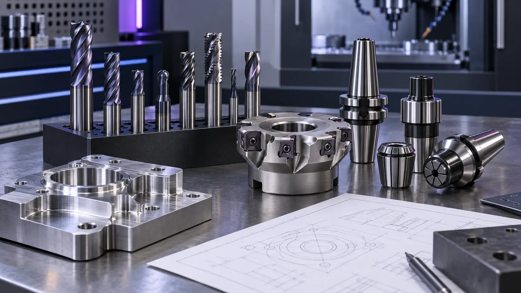
To receive a useful quotation or tooling recommendation, send these details to ZIROO TOOLS:
- Workpiece material grade, hardness, and stock condition.
- Part drawing or 3D model, including tolerance and surface-finish requirements.
- Operation: roughing, finishing, slotting, face milling, contouring, thread milling, or special profile.
- Machine model, spindle speed, toolholder type, coolant method, and available projection.
- Current tool specification and the problem to solve, such as short life, vibration, burrs, or long cycle time.
- Required cutter dimensions, flute count, coating, custom profile, and expected order quantity.
- Sample validation, inspection requirement, branding, packaging, and repeat-order plan.
For OEM or non-standard tooling, our OEM/ODM process starts with your drawing and machining information. This makes it possible to assess geometry, material, coating, inspection points, and production consistency before batch manufacturing.
Frequently Asked Questions
What is the difference between an end mill and a milling cutter?
An end mill is one type of milling cutter. “Milling cutter” also includes face mills, slotting cutters, thread mills, form cutters, and other tools designed for particular milling operations.
Which milling cutter is best for aluminum?
The correct tool depends on the operation and alloy. In many aluminum operations, a sharp polished geometry with sufficient chip space is important to reduce built-up edge. Confirm the alloy, coolant method, feature, and machine speed before choosing a tool.
Which milling cutter is best for hardened steel?
Carbide grade, coating, geometry, machine stability, and hardness range must be considered together. A suitable tool for pre-hardened steel may not be appropriate for a much harder heat-treated material.
When should I use an indexable milling cutter?
Indexable milling cutters are often practical for larger diameters, high-volume removal, and operations where fast edge indexing and a reusable cutter body are valuable. They are not automatically the best choice for every small, deep, or fine-detail feature.
What information is needed for a custom milling cutter?
Provide the part drawing, material, machine and holder information, current tool dimensions, machining issue, target output, and quantity. For special profiles, include all relevant radii, angles, clearance dimensions, and tolerance requirements.
Work With ZIROO TOOLS
Contact ZIROO TOOLS with your drawing, material, machining operation, machine details, current tooling issue, and target quantity. We can review a suitable standard or custom milling cutter approach for your application.