How to Choose End Mill Corner Radius for Mold Machining
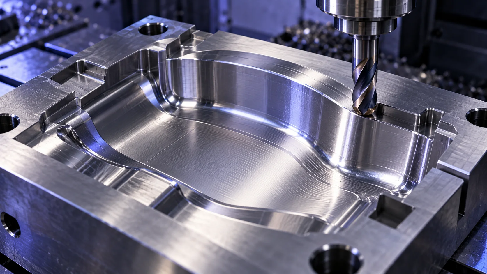
Choosing the right end mill corner radius for mold machining is not simply a matter of choosing a stronger tool. The radius affects whether the cutter can reach an internal feature, how stable the cut is, how much material remains before finishing, and how much hand polishing may be needed later.
For mold cavities, cores, electrodes, and precision wear components, the practical question is usually: What is the largest corner radius that still matches the part geometry and the machining stage? A larger radius can protect the cutting edge, while a smaller radius may be necessary to reach tight internal corners. The correct answer depends on the mold feature, not on a single “best” radius.
This guide explains how to choose a corner radius end mill for mold machining by looking at geometry, machining stage, tool reach, and finishing requirements.
What Is a Corner Radius End Mill?
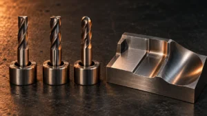
A corner radius end mill, also called a bull nose end mill, has a flat cutting bottom with a radiused transition between the bottom edge and the side cutting edge.
- A square end mill creates a sharp 90-degree corner.
- A ball nose end mill has a fully rounded tip for continuous 3D surfaces.
- A corner radius end mill keeps a flat floor while softening the cutting corner.
This geometry makes corner radius tools useful when a mold feature requires a flat or mostly flat floor, but a sharp cutter corner would be vulnerable during milling. They are often considered for pockets, cavity floors, sidewall transitions, ribs, and semi-finishing operations where the part design allows a radius.
However, a corner radius end mill cannot produce a perfectly sharp internal corner. If the drawing requires a smaller internal radius than the cutter can generate, you must reduce the tool radius, use a smaller tool, or finish that feature with a different tool profile.
Start with the Mold Feature, Not the Tool
The fastest way to make a poor tool choice is to begin with a favorite cutter diameter or a familiar radius. Start with the mold drawing or 3D model instead.
Review these features before selecting the tool:
- Smallest internal corner radius
- Pocket floor geometry
- Sidewall height and draft
- Cavity depth
- Narrow ribs or channels
- Curved or sculpted surfaces
- Required stock allowance for the next operation
- Target surface condition before polishing, EDM, or final finishing
A corner radius tool works best when the part geometry gives it enough room to enter and exit without leaving unacceptable material in the corners.
Check the Smallest Internal Radius
The part’s smallest internal radius sets a hard limit on the tool radius. The cutter’s corner radius must not be larger than the finished internal radius you need to produce.
For example, if a mold pocket contains a small internal fillet, a large-radius bull nose tool may remove material efficiently in open areas but leave excess stock in the tight corner. That may be acceptable during roughing or semi-finishing if a smaller cutter will finish the area later. It is not acceptable if the operation is intended to produce the final geometry.
Before choosing a tool, identify:
- The smallest finished internal radius.
- The smallest region that must be machined by the current operation.
- Whether a later finishing tool is planned.
- Whether any remaining stock is intentional and documented in the CAM strategy.
Check Floor Geometry and Wall Access
A corner radius end mill is usually more suitable for flat floors, shallow forms, shoulders, and transitions than for deeply sculpted surfaces.
Use it when the feature requires:
- A flat bottom with softened corner transitions
- A stable tool for broad cavity floors
- Semi-finishing of accessible regions
- A profile where a small internal radius is acceptable
- More corner support than a sharp square end mill provides
Use a ball nose end mill when the feature requires continuous 3D contouring, deep blended surfaces, tight concave geometry, small internal radii, or fine finishing of complex cavity surfaces.
Use a square end mill when the feature truly requires a sharp internal 90-degree corner, flat-bottom slotting, shoulder milling, or a geometry that does not allow a corner radius.
For a broader overview of profile choices, see ZIROO TOOLS’ guide to end mill types for CNC machining.
How Corner Radius Changes Tool Strength and Finish
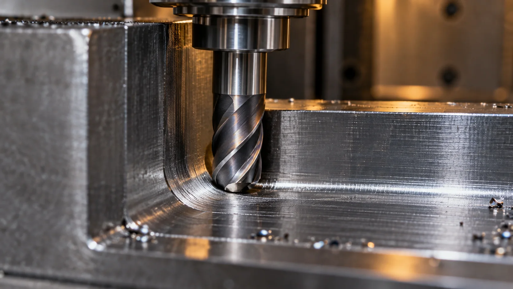
The radius at the cutter corner changes how the cutting edge meets the workpiece. A sharp corner concentrates more load at a small area of the edge. Adding a radius distributes the transition more gradually.
In practical mold machining, that can help when the operation involves repeated sidewall engagement, floor-to-wall transitions, or semi-finishing passes where a sharp tool corner is exposed to changing loads.
But a larger radius is not automatically better. A larger corner radius may offer a more supported cutting edge, yet it also creates a larger fillet in the machined part. If the tool radius is too large for the cavity design, it can leave material in corners or force an additional finishing operation.
A smaller corner radius can access tighter details, but it moves closer to the limitations of a square end mill. The selection should balance:
| Selection factor | Why it matters |
|---|---|
| Minimum internal radius | Determines whether the tool can finish the geometry |
| Tool diameter | Affects rigidity, reach, and access |
| Corner radius | Influences edge support and the fillet left in the workpiece |
| Cavity depth | May require longer reach and increase deflection risk |
| Surface type | Determines whether a flat, corner-radius, or ball profile fits best |
| Machining stage | Roughing, semi-finishing, and finishing have different priorities |
| Remaining stock | Determines whether a later cutter can clean up tight areas |
The goal is not to maximize radius. The goal is to use the largest practical radius that fits the feature plan and machining sequence.
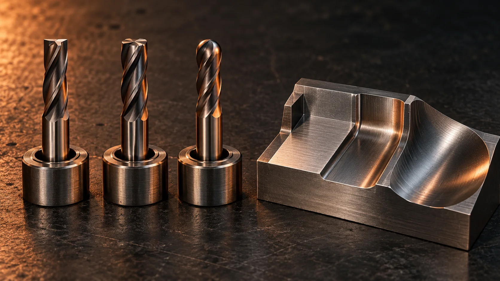
Corner Radius vs. Ball Nose vs. Square End Mill
These three profiles should be treated as complementary tools in a mold machining process, not as interchangeable choices.
| Tool type | Best-fit mold features | Main advantage | Main limitation |
|---|---|---|---|
| Square end mill | Sharp shoulders, flat slots, true corners | Produces a sharp internal corner | Corner edge is less protected |
| Corner radius end mill | Flat floors, shallow forms, pockets, semi-finishing | Combines a flat floor with a supported corner transition | Cannot create a sharp internal corner or every complex 3D surface |
| Ball nose end mill | 3D cavities, blended surfaces, tight concave areas | Follows continuous curved geometry | Less efficient for some broad flat-floor operations |
A practical mold program may use a larger corner radius tool for accessible semi-finishing, a smaller tool for tighter transitions, a ball nose tool for complex 3D finishing, and a square tool only where sharp geometry is required.
Choose the Radius by Machining Stage
Roughing and Semi-Finishing
During roughing, the priority is controlled material removal, access, and leaving suitable stock for later operations. A corner radius tool may be useful when the cavity has broad accessible regions and the final geometry does not require the current tool to enter every tight corner.
During semi-finishing, you want to establish consistent remaining stock before ball nose finishing or localized detail machining. Ask whether the tool can enter the cavity without interference, leave uniform stock, clear the surrounding walls, and remain stable at its required reach.
Finishing Complex 3D Surfaces
For continuously changing 3D surfaces, a ball nose end mill is often the more natural finishing choice because its spherical profile follows curved geometry in multiple directions.
A corner radius end mill may still be appropriate for finishing planar or shallow regions where a flat floor is required. It should not be used just because it seems stronger if the surface geometry actually demands a ball profile.
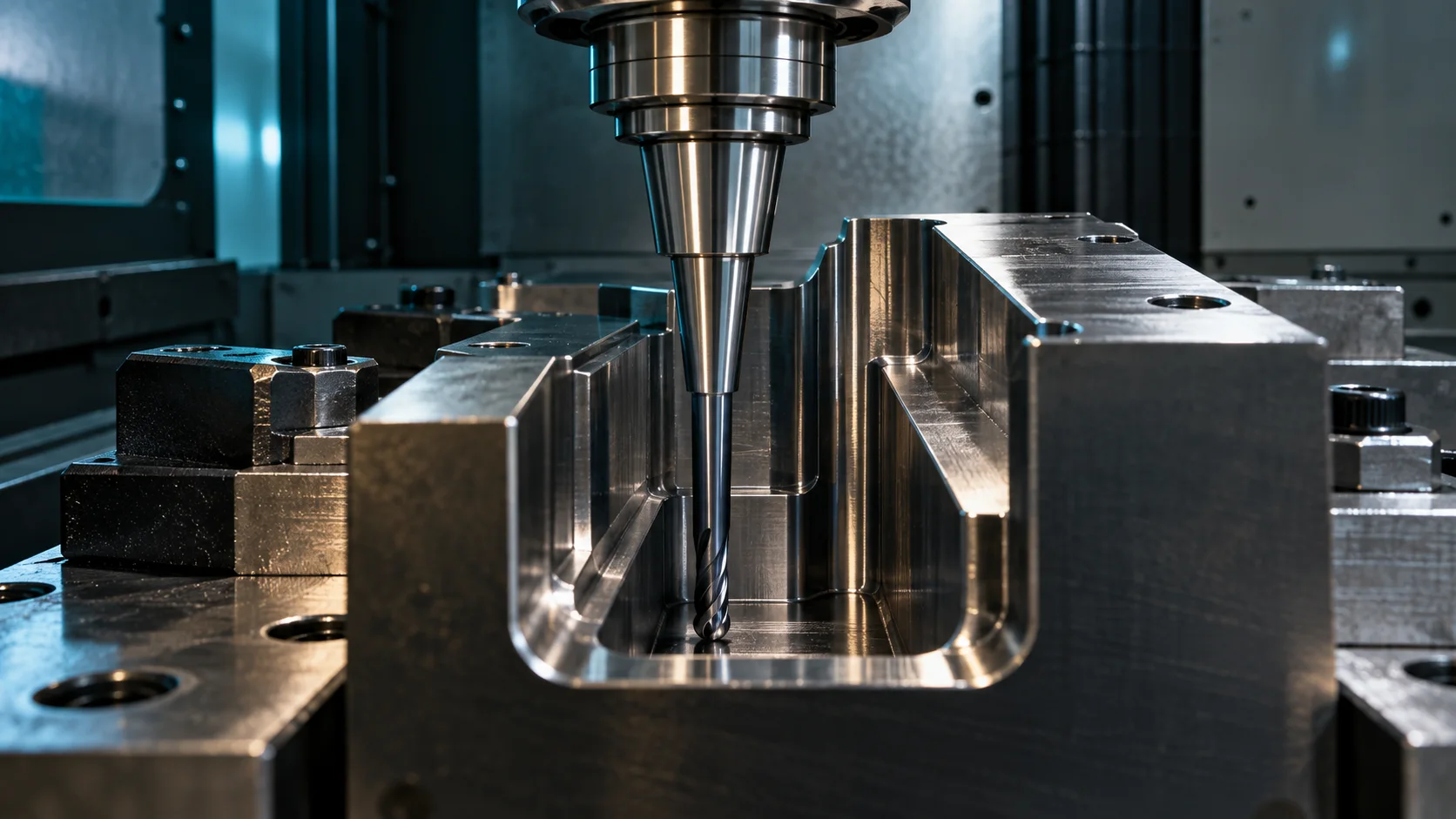
Do Not Ignore Diameter, Reach and Toolholder Setup
Corner radius is only one part of the cutter specification. A correct radius on an unstable tool is still a poor solution.
In deep mold cavities, tool reach and holder clearance can become more important than the radius itself. Longer overhang generally reduces stiffness and increases the risk of deflection, vibration marks, edge damage, and inconsistent surface results.
Before releasing the tool for production, check:
- Cutting diameter
- Corner radius
- Flute length
- Effective reach
- Neck clearance
- Overall projection from the holder
- Toolholder type
- Machine spindle condition and rigidity
- Coolant or air-blast strategy
- CAM collision and holder-clearance verification
For material, flute count, coating, and broader end mill specification decisions, use this related carbide end mill selection guide.
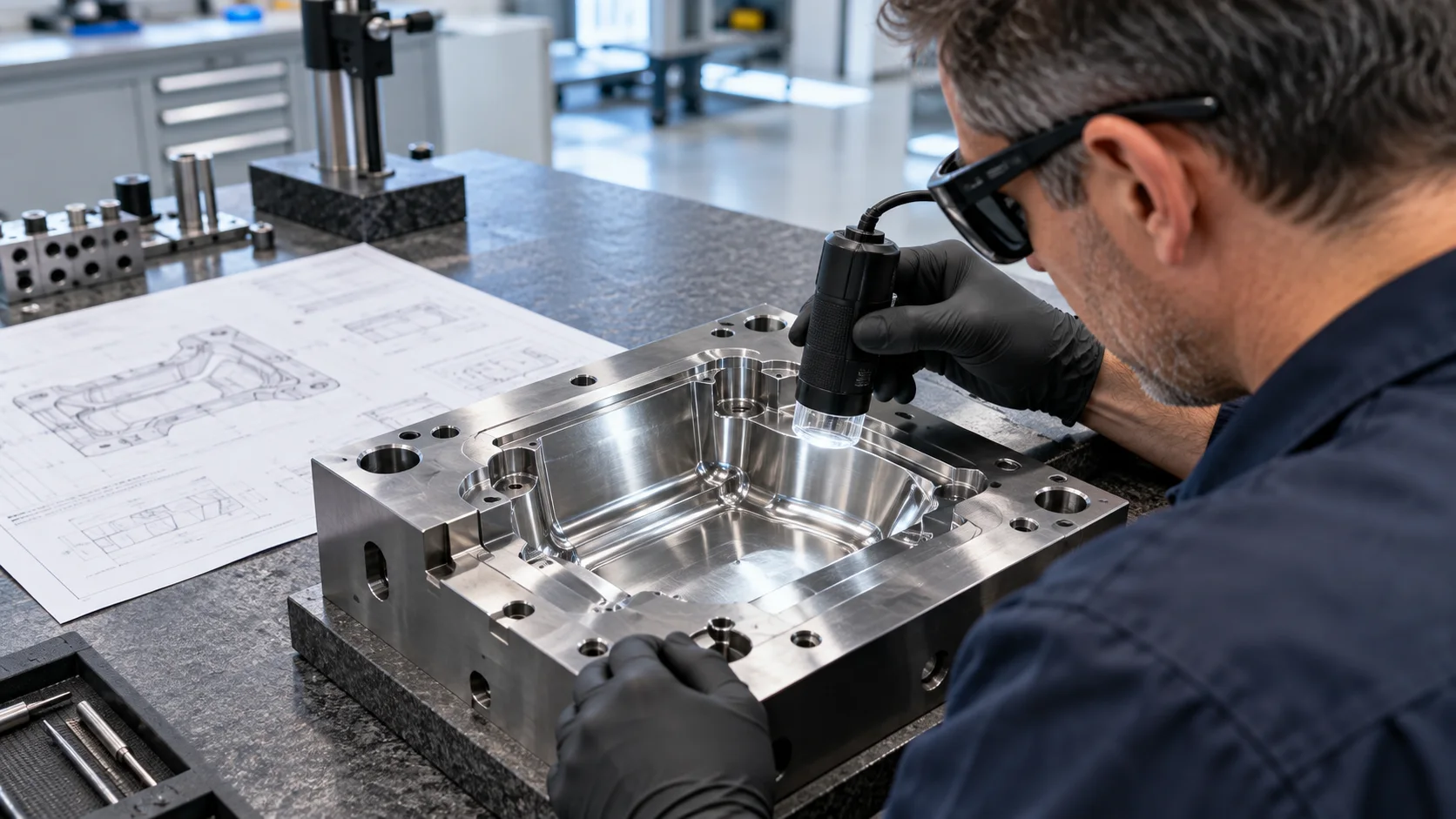
A Practical Selection Checklist
- Read the smallest internal radius on the drawing. This determines the maximum usable tool radius for finished features.
- Separate open areas from tight-detail areas. A larger tool can machine open regions while smaller tools finish local details.
- Define the machining stage. Decide whether the tool is for roughing, semi-finishing, finishing, or a specific transition.
- Match the tool profile to the surface. Use a corner radius tool for flat-floor and accessible transition areas; use a ball nose tool for continuous 3D forms.
- Verify reach, neck clearance, and holder clearance. Confirm that the cutter can access the feature without excessive projection or collision risk.
- Plan the next operation before cutting the first one. Check that remaining material will be accessible to the next tool and that the stock allowance is intentional.
Common Mistakes to Avoid
Selecting Radius Only by Material
Mold steel grade matters, but it is not enough. The same material may require very different tools for a shallow cavity floor, a deep narrow rib, or a complex 3D insert.
Choosing the Largest Radius Without Checking the Model
A large radius may improve edge support, but it can leave unwanted material in tight internal corners. Always check the smallest required feature first.
Using One Tool for Every Cavity Area
Open floors, steep walls, tight fillets, and 3D contours often need different tool profiles or diameters. A multi-tool strategy can be more controlled than forcing a single cutter to complete all regions.
Ignoring Tool Reach
A technically correct radius cannot solve problems caused by excessive overhang or holder interference. Confirm the full assembly, not only the cutter geometry.
Treating Semi-Finishing as an Unimportant Pass
Poor semi-finishing can leave uneven stock, which makes final finishing less predictable. Use this stage to prepare consistent material for the finishing tool.
Frequently Asked Questions
What corner radius should I use for mold machining?
Use a radius that is no larger than the smallest internal fillet the operation must produce. Then consider the cutter diameter, access, reach, and whether another tool will finish tighter details.
Is a corner radius end mill better than a ball nose end mill for molds?
Neither is always better. A corner radius tool is useful for accessible flat floors and transitions, while a ball nose tool is generally more suitable for continuous 3D surfaces and tight concave areas.
Can a corner radius end mill machine sharp internal corners?
No. A corner radius tool leaves a fillet. Use a square end mill or another suitable process when the drawing requires a true sharp internal corner.
Should I use a larger corner radius for hardened mold steel?
Do not choose radius by hardness alone. Material condition is important, but you must first confirm geometry, cutter reach, machine rigidity, machining stage, and required finish.
When should I use a bull nose end mill for semi-finishing?
Use it when the cavity includes accessible areas with flat or shallow geometry, and when its radius will leave controlled stock for the finishing operation.
What information should I send when requesting a mold machining cutter?
Provide the material and heat-treatment condition, CAD drawing or key dimensions, smallest internal radius, cavity depth, machining stage, machine and holder setup, maximum tool reach, and target surface condition.
Choose the Radius as Part of the Whole Process
The correct end mill corner radius for mold machining comes from the relationship between the part geometry and the process plan. Start with the smallest internal radius, separate open areas from tight details, and then match the cutter profile, diameter, reach, and machining stage.
A corner radius end mill can be a highly practical choice for mold cavity floors, transitions, and semi-finishing. But it should be selected as part of a complete toolpath plan—not as a universal replacement for ball nose or square end mills.
If you are selecting tooling for a mold cavity, contact ZIROO TOOLS with your drawing, material, smallest internal radius, cavity depth, machine setup, and machining stage. Our team can help you identify the cutter geometry to evaluate for your application.