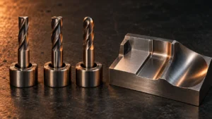
Micro drill bits are used to produce very small, accurate holes in parts where ordinary drills are too large, too flexible, or unable to meet the required hole quality. This specialized form of precision hole making supports printed circuit boards, electronic components, medical instruments, aerospace parts, watches, jewelry, precision molds, nozzles, and miniature mechanical components.
However, selecting a micro drill is not only a matter of choosing the required diameter. The workpiece material, hole depth, tolerance, spindle condition, tool holding, coolant delivery, and chip evacuation strategy all affect the result. A drill that works well in a shallow aluminum hole may fail quickly in stainless steel or a deep blind hole.
This guide explains what micro drill bits are used for, how their applications differ by industry, how to select a suitable tool, and what information a supplier needs before recommending a standard or custom solution.
What Is a Micro Drill Bit?
A micro drill bit is a precision cutting tool designed to create small-diameter holes. There is no single universal diameter that separates a micro drill from a conventional drill in every industry. Instead, the term generally describes drills small enough that tool rigidity, spindle runout, chip evacuation, and handling become critical process factors.
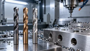
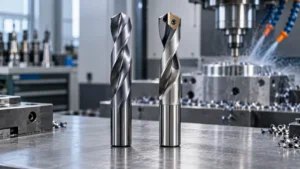
Like a conventional twist drill, a micro drill normally has cutting lips, flutes, a point, a margin, and a shank. The proportions and geometry are adapted for small-hole machining. Many designs use a shank larger than the cutting diameter to improve clamping and stiffness. The flute geometry must remove chips without weakening the already slender tool body.
As diameter decreases, even a small amount of radial runout becomes significant relative to the tool size. This can make one cutting edge carry more load than the other, resulting in an oversized hole, poor surface finish, rapid wear, or sudden breakage. For this reason, micro drilling is a system-level process involving the tool, holder, spindle, workpiece setup, coolant, and cutting parameters.
What Are Micro Drill Bits Used For?
Micro drill bits are used wherever a component needs small, repeatable holes with controlled position, diameter, and surface quality. The exact tool design depends on the part material and the function of the hole.
PCB and Electronics Manufacturing
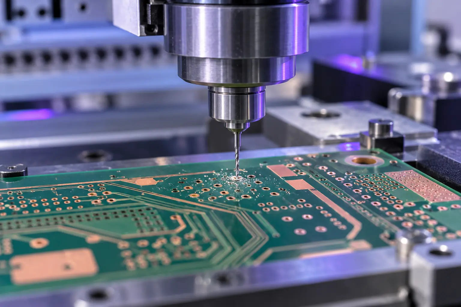
Printed circuit boards contain many small holes for component leads, vias, mounting features, and electrical interconnections. PCB drilling may involve copper layers, resin, and glass-fiber-reinforced material. These layers can create abrasive wear and place different demands on the cutting edge.
Production PCB drilling therefore requires more than a small diameter. Manufacturers consider hole-wall quality, positional accuracy, burr control, tool wear, and consistent performance across a large number of holes. Carbide micro drills are widely used because their stiffness and wear resistance suit high-speed, repetitive drilling, provided the machine and handling conditions are stable.
Medical Device Components
Medical and dental machining may require micro holes for fluid passages, vents, dosing features, miniature fasteners, or instrument functions. Possible workpiece materials include stainless steels, titanium alloys, engineering plastics, and other application-specific materials.
The drilling process must be selected around the material, required finish, burr limits, and cleaning requirements. A supplier should review the drawing and application rather than assume that one general-purpose micro drill can cover every medical component.
Aerospace and Precision Engineering
Aerospace machining applications use small holes in sensors, fluid-control components, instrumentation, and parts requiring controlled airflow or cooling. These holes may be machined in heat-resistant alloys, stainless steels, aluminum alloys, or other engineered materials.
Difficult materials increase cutting forces and heat, while deep or angled holes complicate chip evacuation and tool entry. Tool geometry, coating, coolant strategy, and setup rigidity must therefore be evaluated together. Fixed cutting data copied from a different tool or material is not a reliable starting point.
Watchmaking and Jewelry
Watches, jewelry, and decorative metal components often contain small holes for pins, settings, links, screws, and assembly features. The parts may be small, thin, valuable, or easily marked, so secure workholding and accurate tool entry are essential.
Depending on the material and production method, the priority may be a clean entry, low burr formation, dimensional control, or protection of a finished surface. Prototype and manual work also require extra care because handheld equipment typically cannot match the runout control and alignment of a precision spindle.
Molds, Nozzles, and Small Mechanical Parts
Micro drills are also used for vent holes in molds, small passages in nozzles, lubrication holes, miniature mechanical assemblies, and instrument components. Blind holes create a particular chip-packing risk because chips cannot exit through the far side of the workpiece.
For these parts, the buyer should specify whether the hole is blind or through, the required depth, entrance and exit conditions, and any restrictions on burrs or surface finish. These details can change the recommended flute length, geometry, and drilling cycle.
What Materials Can Micro Drill Bits Machine?
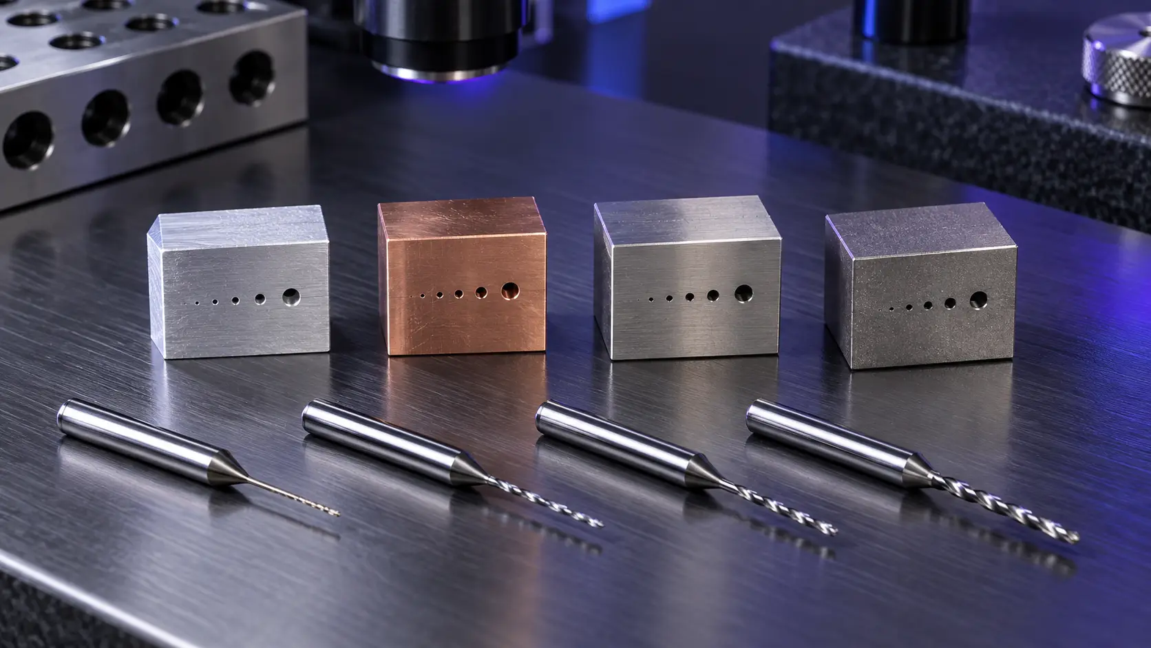
A micro drill can be designed for many materials, but tool selection should be material-specific. The table below summarizes common concerns rather than prescribing universal cutting data.
| Workpiece material | Main machining risks | Selection priorities |
|---|---|---|
| PCB composites | Abrasive glass fibers, resin smearing, hole-wall defects | Wear-resistant tool material, suitable geometry, controlled runout |
| Aluminum and copper | Material adhesion, built-up edge, chip packing | Sharp cutting edge, effective flute space, suitable lubrication |
| Carbon and alloy steels | Heat, edge wear, increasing cutting force | Tool rigidity, substrate and coating selection, stable parameters |
| Stainless steel | Work hardening, heat, difficult chip control | Sharp geometry, reliable feed, cooling and chip evacuation |
| Titanium and heat-resistant alloys | Heat concentration, adhesion, rapid wear | Application-specific geometry, coating, cooling and conservative validation |
| Plastics and engineering composites | Melting, delamination, burrs, dimensional recovery | Sharp edges, heat control, support and material-specific geometry |
The correct choice cannot be made from the material name alone. Grade, hardness, part geometry, hole depth, coolant access, and required output also matter. When requesting a recommendation, provide the complete material designation whenever possible.
How to Choose the Right Micro Drill Bit
1. Define Hole Diameter and Tolerance
Start with the finished hole requirement, not only the nominal drill diameter. Specify the acceptable hole tolerance, roundness, position, entrance condition, and whether a subsequent operation will finish the hole. If the requirement is extremely tight, drilling may be followed by suitable carbide reaming tools as part of a broader hole-finishing process.
Also indicate whether the diameter is standard or non-standard. A custom tool may be appropriate when the required size, step, point form, or feature cannot be produced efficiently with a catalog drill.
2. Compare Hole Depth With Drill Diameter
The relationship between hole depth and diameter is more useful than depth alone. A deeper length-to-diameter ratio increases the difficulty of delivering coolant, removing chips, and maintaining a straight hole. It may also require a pilot operation, a specialized geometry, or a controlled drilling cycle.
Do not select an unnecessarily long flute length. Extra reach reduces rigidity and can amplify vibration or deflection. Use the shortest practical cutting length and overhang that safely reaches the feature.
3. Choose Between Carbide, HSS, and Cobalt HSS
Solid carbide micro drills offer high stiffness, wear resistance, and suitability for precise, high-speed production. Their rigidity helps maintain geometry, but carbide is brittle and requires stable clamping, low runout, and careful handling.
High-speed steel is tougher and may tolerate less rigid conditions better, although it generally has lower wear resistance and stiffness than carbide. Cobalt-alloyed HSS can improve hot hardness for certain applications. The best material depends on the workpiece, equipment, production volume, and failure mode—not on a simple claim that one material is always superior.
4. Review Point Geometry, Flutes, and Coating
Point angle, web design, cutting-edge preparation, flute form, and margin geometry influence centering, cutting forces, chip formation, and hole quality. A geometry developed for free-cutting aluminum may not perform the same way in stainless steel or abrasive PCB material.
Coatings can improve wear resistance, heat management, or resistance to material adhesion in suitable applications. However, coating thickness and edge sharpness matter more as tools become smaller. Coating should therefore be chosen with the substrate, geometry, workpiece, and cutting environment.
5. Confirm Machine, Holder, and Coolant Conditions
Before ordering the tool, confirm that the spindle can provide the required speed range with acceptable runout. Inspect the collet or holder, minimize overhang, and keep clamping surfaces clean. A high-quality drill cannot compensate for a damaged holder or unstable spindle.
Coolant strategy depends on the application. Some operations use external coolant, mist, air, or another controlled method; specialized deep-hole tools may use internal coolant. The goal is to manage heat and remove chips without deflecting the small tool.
How to Use Micro Drill Bits Without Breaking Them
- Verify spindle and holder condition. Measure runout close to the tool and inspect the collet, holder, and spindle interface.
- Use secure workholding. Prevent movement, vibration, or unsupported flexing of thin parts.
- Minimize tool overhang. Clamp the tool as short as the application safely permits.
- Prepare the entry condition. Flat, stable entry helps prevent walking. Angled or curved surfaces may need an application-specific approach.
- Use tool-specific starting data. Base speed and feed on the tool supplier's guidance, then validate for the actual material, machine, diameter, and depth.
- Maintain a controlled feed. Feeding too slowly can create rubbing and heat, while excessive feed can overload the cutting edge.
- Manage chips. Adjust the cycle, coolant, and withdrawal strategy when chips cannot leave the hole reliably.
- Monitor wear and hole quality. Replace the drill before progressive wear creates unstable cutting or damages valuable parts.
Peck drilling is sometimes used to assist chip evacuation, but it is not automatically the best method for every micro-drilling operation. Excessive or poorly controlled pecking can add cycle time and repeated entry loads. The cycle should be matched to the tool design, hole depth, material, and coolant method.
Why Do Micro Drill Bits Break?
| Observed problem | Possible causes | Checks and corrective direction |
|---|---|---|
| Drill breaks at entry | Runout, angled entry, excessive feed, unstable part | Check alignment, entry geometry, clamping, and initial parameters |
| Drill breaks inside the hole | Chip packing, excessive depth per cycle, inadequate cooling | Inspect chips, flute loading, coolant access, and drilling cycle |
| Oversized or tapered hole | Runout, deflection, worn edge, excessive overhang | Measure runout, reduce overhang, inspect wear, verify holder condition |
| Heavy burrs | Dull tool, incorrect geometry, poor support at breakthrough | Inspect the edge, review geometry and exit support |
| Rapid wear | Wrong substrate or coating, abrasive material, heat, unsuitable parameters | Confirm material grade, cooling, cutting data, and tool specification |
| Hole position error | Tool walking, fixture movement, spindle or machine error | Review entry preparation, fixture stability, runout, and machine accuracy |
A broken micro drill is often the final symptom of a process problem rather than proof that the tool material is defective. Record where the tool breaks, inspect the chips and hole, and compare results over multiple tools before changing several variables at once.
Micro Drill Bit Purchasing Checklist
Providing complete information helps a supplier recommend a tool more efficiently. Include the following details in your request for quotation:
- Workpiece material, grade, and hardness when known
- Required hole diameter and tolerance
- Hole depth and required length-to-diameter ratio
- Through hole, blind hole, angled entry, or intersecting hole
- Required position, surface finish, and burr limits
- Machine type, spindle speed range, and holder information
- Coolant or lubrication method
- Production quantity and target cycle conditions
- Current tool, current problem, and expected improvement
- Part drawing or hole detail, if available
This information is especially important for small tools because minor changes in reach, entry condition, material, or setup can substantially affect performance.
When Do You Need a Custom Micro Drill?
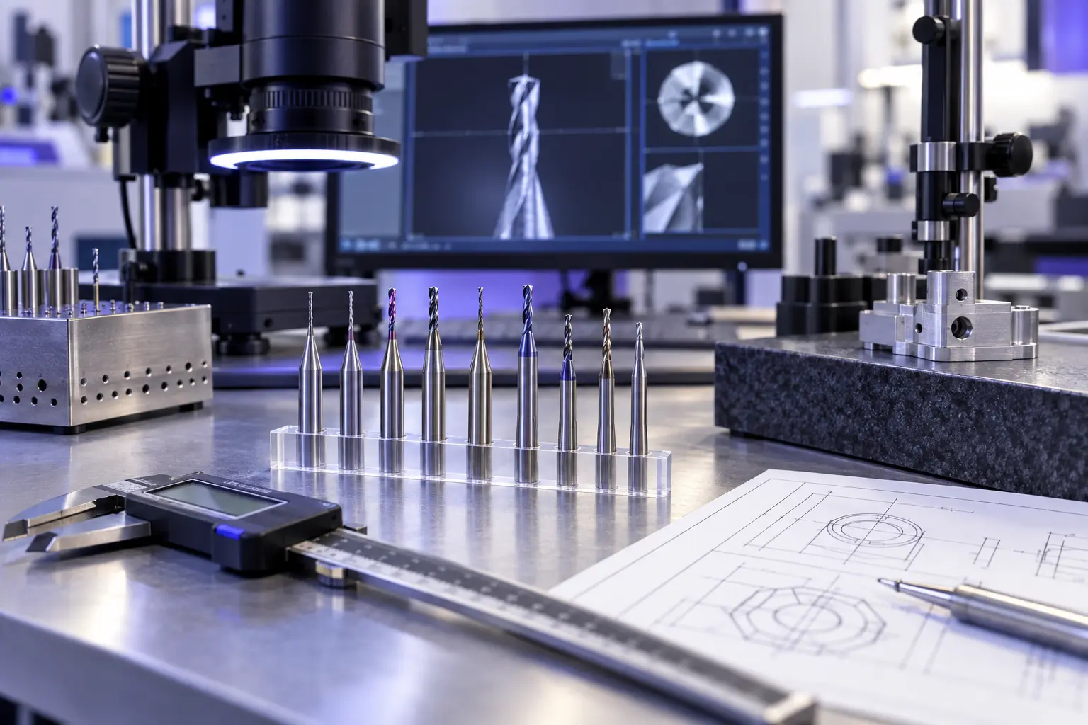
A standard micro drill is usually the most economical choice when its diameter, reach, and geometry match the operation. A custom design becomes worth evaluating when the application needs a non-standard diameter, special flute length, step feature, unusual point geometry, restricted access, or material-specific cutting geometry.
Custom CNC cutting tools can also reduce the number of operations when one tool can safely combine compatible features. However, the design must be based on the drawing and machining conditions. Buyers should compare not only tool price but also process stability, tool-change time, scrap risk, inspection requirements, and total cost per acceptable part.
ZIROO TOOLS can review your drawing and machining information to evaluate an appropriate micro-drilling solution. Recommendations should be confirmed through controlled testing under the customer's actual production conditions.
Frequently Asked Questions
What sizes are considered micro drill bits?
There is no single industry-wide cutoff used in every application. The term generally refers to small-diameter drills for which runout, rigidity, chip evacuation, and handling become critical. Always confirm the supplier's stated diameter range and application definition.
Are carbide micro drills better than HSS?
Carbide offers high stiffness and wear resistance, making it suitable for stable, precise production. HSS is tougher and may be more forgiving in less rigid setups. The better option depends on the material, machine, hole depth, volume, and dominant failure risk.
Can micro drill bits drill stainless steel?
Yes, when the tool geometry, material, coating, coolant, and cutting data are appropriate for the stainless-steel grade. Work hardening, heat, and chip control must be managed, so avoid using parameters intended for aluminum or PCB material.
Can micro drills be used for PCB manufacturing?
Yes. PCB manufacturing is a major micro-drilling application. Tool wear, positional accuracy, hole-wall quality, burrs, and the abrasive effect of reinforced board materials should be considered when selecting the drill and process.
Why do micro drill bits break easily?
Their small cross-section gives them limited resistance to bending and overload. Common causes include excessive runout, unstable clamping, chip packing, unsuitable feed, too much overhang, poor entry conditions, or progressive wear.
Do micro drill bits require a high-speed spindle?
Small diameters often require higher rotational speeds to reach an appropriate cutting speed, but the required value depends on the tool and material. Speed alone is not enough; spindle runout, balance, holder condition, and feed control are equally important.
How do you drill deep micro holes?
Deep micro holes may require a purpose-designed tool, pilot operation, controlled drilling cycle, effective cooling, and reliable chip evacuation. Define the length-to-diameter ratio and follow tool-specific guidance rather than applying a general peck cycle automatically.
What information is needed to order custom micro drills?
Provide the material, hole diameter and tolerance, depth, hole type, required quality, machine and holder details, coolant method, production volume, and a drawing. Also explain the current failure or improvement target.
Conclusion
Micro drill bits are used to create small precision holes in PCBs, electronics, medical components, aerospace parts, watches, jewelry, molds, nozzles, and miniature mechanical assemblies. Successful micro drilling depends on more than diameter: the tool material, geometry, hole depth, workpiece, spindle runout, clamping, cooling, and chip evacuation must work as one process.
For a practical recommendation, contact ZIROO TOOLS with your part drawing, workpiece material, required diameter and tolerance, hole depth, machine information, and current machining problem. Our team can review the application and discuss a standard or custom micro-drilling solution.