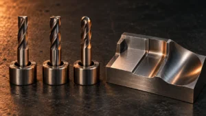
Choosing carbide taps for hardened steel starts with the workpiece and the thread, not with a coating or a hardness number in isolation. The steel grade, heat-treatment condition, actual hardness, hole type, thread tolerance, tap-drill size, machine rigidity, and production target all affect whether a carbide tap is suitable. A mismatch can lead to chipped cutting edges, broken taps, damaged threads, or an expensive part that cannot be recovered.
This guide gives you a practical sequence for evaluating a carbide tap for hardened-steel work. You will learn what information to confirm, how to compare carbide with HSSE or powder-metallurgy taps and thread milling, what to inspect in the hole and machine setup, and how to validate a candidate before production. The goal is not to prescribe one tap for every steel condition. It is to help you ask the right questions, reduce avoidable trial-and-error, and compare candidate processes against your drawing and acceptance criteria.
Use the recommendations for the exact tap model you select; manufacturer data takes precedence over general guidance. If the material condition or thread specification is uncertain, resolve that information before a production trial rather than treating a generic hardness category as a complete application description.
Why Tapping Hardened Steel Is Different
A tap cuts several thread flanks at once inside a confined hole. That creates torsional load while leaving limited room for chips, heat, and tool deflection to escape. Hardened materials can raise cutting forces and accelerate edge wear, while the small cross-section of a tap leaves little room for error. Solid carbide is hard and wear resistant, but it is less tolerant of impact and misalignment than tougher steel-based tool materials.
“Hardened steel” does not identify a complete machining condition. A pre-hardened mold steel, a fully hardened tool steel, a case-hardened component, and a hardened stainless grade can behave differently. Hardness may vary through a case-hardened layer, and the drawing may describe a heat-treatment target rather than the measured condition at the thread. Confirm the material grade, heat-treatment state, hardness range, and location of the thread before choosing a tap.
- High torque: An undersized or incorrectly prepared tap-drill hole can increase the material engaged by the tap.
- Edge chipping or fracture: Runout, misalignment, vibration, poor clamping, or impact during entry can damage a carbide edge.
- Chip packing: Chips trapped in a blind hole can raise torque or jam the tap near the bottom.
- Thread defects: Incorrect thread allowance, tap condition, synchronization, or inspection can produce threads outside the drawing requirements.
- High recovery cost: A broken tap in a valuable mold or precision part may require specialized removal or make the workpiece unusable.
Before selecting a tool, review the full application rather than treating hardness as the only variable. Manufacturers also caution that actual cutting data depends on the tool design and setup. For example, Seco’s material-driven tapping guidance notes that material properties and conditions such as the machine, holder, coolant, and clamping can affect results.
When Is a Carbide Tap a Suitable Option?
A carbide tap is worth evaluating when the selected tool is designed for the material condition and the process can support controlled, repeatable engagement. This may include stable CNC production where wear resistance, thread consistency, or the cost of repeated tool changes is important. The suitability of any tap depends on its manufacturer’s stated application range and the workpiece condition, not on the word “carbide” alone.
Before specifying one, check that the setup has:
- A machine and tapping cycle capable of controlling feed and spindle synchronization for the selected tap.
- A suitable holder in good condition, with low runout and secure clamping.
- Workholding that prevents movement or vibration during entry, cutting, and reversal.
- A tap-drill hole and entry chamfer that meet the tool and thread requirements.
- A coolant or lubrication approach consistent with the tap maker’s instructions.
- A defined inspection method for thread size, fit, depth, and surface condition.
If these conditions are unknown, establish them before moving to production. A different tap material or a thread-milling process may be more appropriate when the setup cannot control alignment, when the part is unusually valuable, or when recovery from a broken tap would be unacceptable. Treat these alternatives as options to evaluate, not universal replacements.
Coating selection belongs after the basic tool and process match. A coating cannot compensate for a tap that is outside its approved material range, a tap-drill hole that is too small, or a holder that allows excessive runout. Ask for the tap maker’s recommended coating and substrate for the actual work material, hardness, coolant condition, and cutting strategy. Compare coated and uncoated options only when the tool geometry and trial conditions are otherwise comparable.
Be cautious with broad claims such as “best coating for hardened steel” or a fixed multiplier for tool life. Coating results can depend on the substrate, preparation, geometry, workpiece, lubrication, and machine. If a supplier recommends a specific coating, request the corresponding product data and validate the result on a representative job.
Carbide Tap vs. HSSE-C or PM Tap vs. Thread Milling
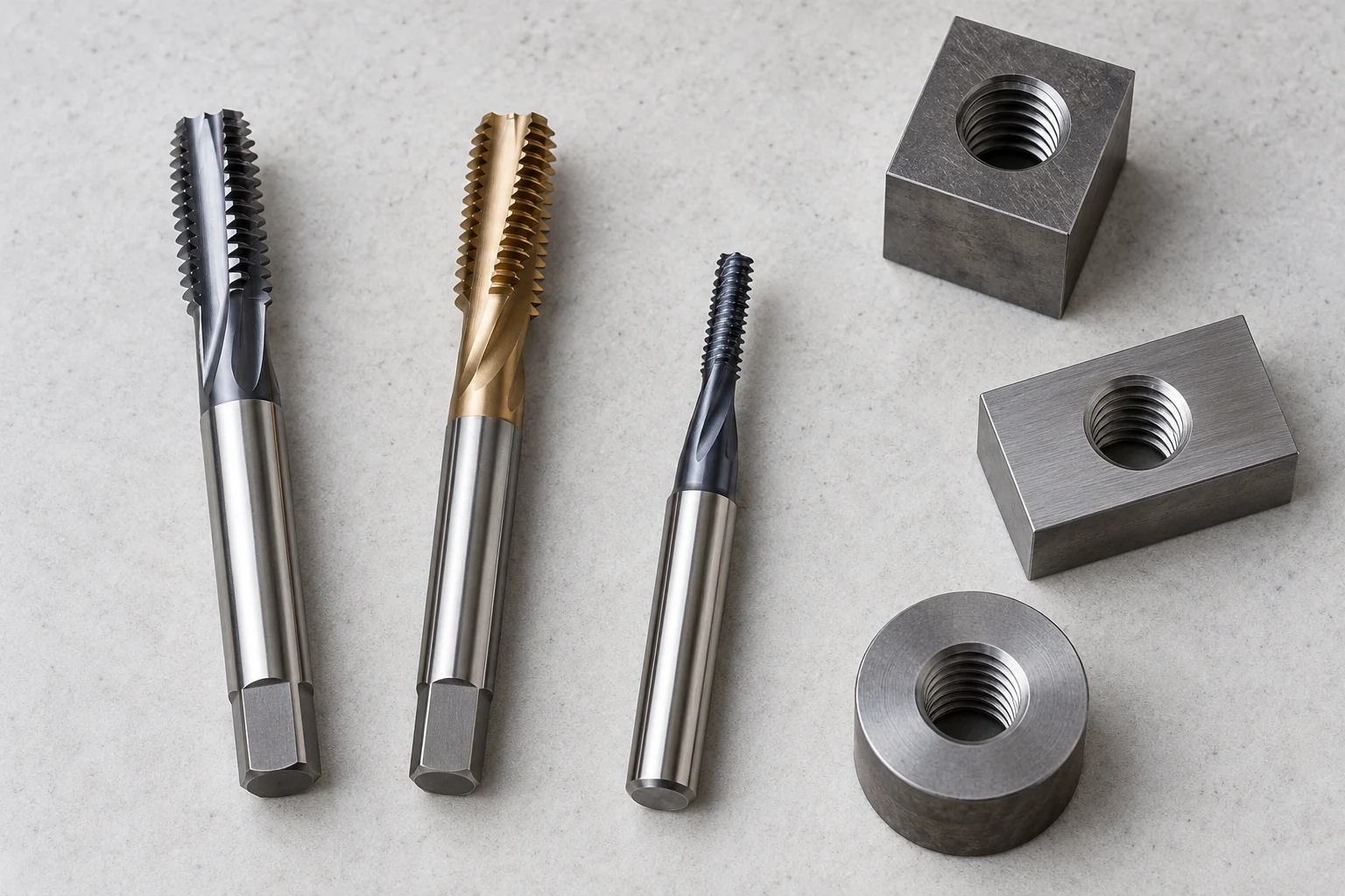
Compare the full process rather than the purchase price of one tool. The following table is a screening guide; confirm material compatibility and operating instructions for the exact product and application.
| Decision factor | Solid carbide tap | HSSE-C or PM tap | Thread milling |
|---|---|---|---|
| Typical consideration | Evaluate for demanding wear conditions and stable CNC setups when the tap maker approves the material. | Evaluate when toughness and tolerance for less ideal conditions are important, subject to the tool’s material range. | Evaluate when CNC capability and programming support are available and tapping risk or thread flexibility matters. |
| Setup sensitivity | Requires careful alignment, low runout, and controlled engagement. | May tolerate some variations better, depending on tap design and size. | Depends on machine accuracy, interpolation, tool reach, and correct programming. |
| Chip management | Must match tap geometry, hole type, depth, and coolant strategy. | Must also match chip direction and hole type. | Produces chips differently; verify clearance and the recommended milling strategy. |
| Thread-size adjustment | A tap generally produces its specified thread form and size; adjustment is limited by tool choice and process. | Similar constraints apply; select the correct tap and tolerance for the drawing. | Program and tool choice can offer adjustment within the tool’s capabilities. |
| Primary risk to assess | Chipping or breakage if the setup or application is unsuitable. | Wear, deflection, and tool-life limits in the actual hardness condition. | Cycle time, toolpath, reach, and machine capability. |
| Cost comparison | Include tool cost, inspection, tool changes, downtime, and recovery risk. | Include consumption rate and process stability, not only the initial price. | Include programming, cycle time, tool cost, and scrap exposure. |
HSSE-C refers to cobalt high-speed steel; PM refers to powder-metallurgy tool steel. Both are broad material families, so confirm the specific tap grade and its stated work-material range. There is no universal winner. For a high-value part, the consequence of a trapped tap may outweigh the difference in cycle time. For a stable repeat job, a dedicated tap may be economical if it passes validation. Compare alternatives on the same workpiece, drawing requirements, acceptance criteria, and production conditions.
Step 1: Confirm the Workpiece and Thread
Use the part drawing and process documentation to collect the following before asking a supplier to recommend a tap:
- Material grade and relevant product condition.
- Heat-treatment state and measured or specified hardness range.
- Whether the thread crosses a hardened case, coating, or other surface layer.
- Thread standard, nominal size, pitch, tolerance class, and required fit.
- Required full-thread depth and total hole depth.
- Blind-hole or through-hole status, entry shape, and available clearance.
- Quantity per part, expected batch size, and production frequency.
Do not infer hardness or thread tolerance from a broad material name. If the drawing is incomplete, resolve the missing specification with the design or quality team before cutting. If a coating or finishing operation follows tapping, check whether the thread dimensions must account for that operation.
If the same component also needs holes drilled in hardened steel, see our drill bits for hardened steel guide for the preceding hole-making operation.
Step 2: Match Tap Geometry to the Hole
Tap geometry influences cutting action, chip direction, strength, and usable thread depth. Select it by the material, hole type, thread depth, and tool maker’s application notes.
Through holes
A through hole may provide a path for chips to move ahead of or through the workpiece, depending on the tap style. Confirm there is enough clearance beyond the hole and that chips will not damage a surface or interfere with the fixture. Do not assume that a geometry recommended for long-chipping materials will automatically suit a hardened-steel application.
Blind holes
A blind hole leaves limited space for chips and for the tap’s chamfer. Check the tap’s cutting direction and chip-control design, required full-thread depth, chamfer length, total hole depth, and bottom clearance. The drilled depth must account for the tap geometry and any chips that may collect at the bottom. Follow the exact tap manufacturer’s instructions.
Flute, chamfer, and reach
Flute design should be considered with chip behavior and hole type. Chamfer length affects how close the thread can approach the bottom of a blind hole. Long reach or excessive tool overhang can make alignment and vibration more difficult. Confirm the dimensions in the product drawing instead of selecting by a generic “straight,” “spiral,” or “gun” label alone.
Step 3: Verify the Tap-Drill Hole and Thread Allowance
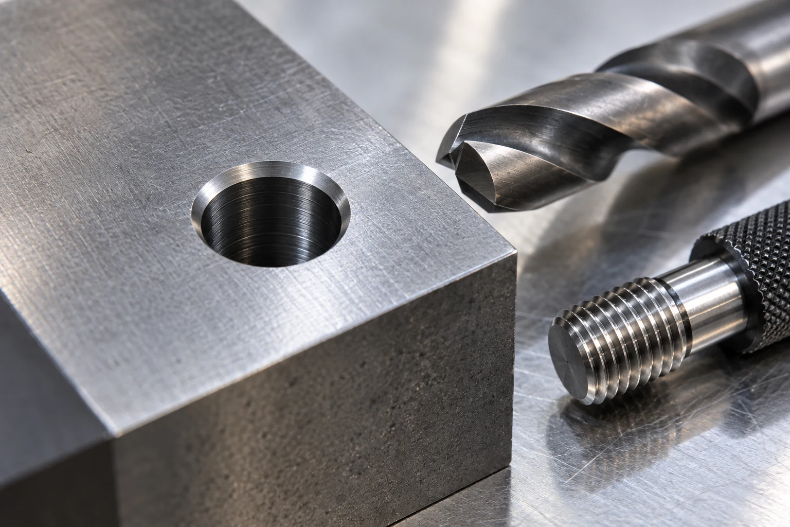
The tap-drill hole strongly affects the amount of material removed and the load on the tool. A hole that is too small can increase torque and breakage risk; a hole that is too large can leave a thread that does not meet the required profile or strength. Use the tap maker’s chart together with the thread drawing, tolerance requirements, and quality acceptance criteria.
Before production, verify:
- The actual drilled-hole diameter, not only the programmed nominal value.
- The hole’s roundness, position, and entry chamfer where these affect engagement.
- The tap’s specified thread tolerance and compatibility with the drawing.
- The total hole depth and bottom clearance against the tap chamfer and required thread depth.
- The measurement method and gauge used to accept the thread.
Never copy a tap-drill value from a different thread standard or tap model. Product-specific manufacturer guidance illustrates why: Yamawa’s guidance for its EH-CT taps discusses bored-hole size, thread tolerance, chamfer length, and bottom clearance for that particular tap family. Those details are not universal specifications.
For related drilling, boring, and hole-finishing operations, review ZIROO TOOLS’ hole-making tools range.
Step 4: Check the CNC Setup Before Tapping

Carbide tap performance is sensitive to uncontrolled motion. Inspect the complete tool path before the first cut, especially on small thread sizes or valuable components.
- Machine: Confirm that the machine and cycle support the required tapping synchronization and reversal behavior.
- Spindle and holder: Check cleanliness, wear, clamping, and runout according to the machine and holder instructions.
- Alignment: Confirm that the hole axis, tool axis, and entry condition are aligned.
- Overhang: Use only the reach needed to access the thread while preserving clearance.
- Workholding: Secure the part so it cannot shift or flex during entry and reversal.
- Coolant and lubrication: Use the method and fluid recommended for the specific tap and material.
- Program: Verify pitch-synchronized feed, depth, reversal, and any peck or step-feed instruction from the tap maker.
Do not assume a slower speed or a pecking cycle is always safer. The right parameters and cycle depend on the exact tap geometry, machine, material, and hole. Start with the product’s published data and perform a controlled test.
As one product-specific example, OSG’s EXOCARB VX-OT guide calls for a rigid machine and toolholder and gives other instructions for that series. Use its values only for the listed products, and consult the instructions for whichever tap model you select.
How to Reduce Carbide Tap Breakage
When a tap fails, record where and how it failed before changing tools or parameters. The location can help narrow the diagnosis, but it is not enough by itself to prove a single cause.
| Observed issue | Checks to make first | Next validation step |
|---|---|---|
| Chipped at entry or first thread | Alignment, runout, entry chamfer, workholding, spindle movement, and start synchronization. | Inspect the hole and tool under magnification; confirm entry conditions and run a controlled single-hole test. |
| Breaks near the bottom of a blind hole | Total hole depth, full-thread depth, tap chamfer length, bottom clearance, and chip accumulation. | Verify drilled depth and chip path against the specific tap’s drawing and instructions. |
| Torque rises or chips jam | Tap-drill diameter, material condition, chip direction, coolant access, and cycle instructions. | Check measured hole size and review chip evidence after a short test. |
| Thread size or finish is inconsistent | Tap wear, tool runout, feed synchronization, material variation, and gauge method. | Use consistent inspection and compare the thread to drawing acceptance criteria. |
| Tap life changes between batches | Material or heat-treatment variation, holder condition, coolant, and operator or program changes. | Compare recorded process data across batches and isolate one variable at a time. |
Stop and follow site procedures before inspecting or removing a tool. Do not reach into a machine while it is running. If a tap breaks in a valuable part, follow the site’s recovery and quality procedure before attempting removal.
A Controlled Trial Before Production

Validate the candidate tap on representative material and with the intended machine, holder, coolant, and program. A test on a different steel condition or a less demanding hole may not predict the production result.
- Record the inputs: material grade, heat treatment, hardness, thread specification, hole type and depth, measured tap-drill diameter, and required tolerance.
- Record the setup: machine, holder, runout check, overhang, workholding, coolant or lubricant, and program version.
- Use the selected model’s starting data: follow the product documentation and note any approved adjustments.
- Inspect at defined intervals: check thread size, fit, finish, depth, burrs, tool condition, and chip behavior.
- Compare alternatives consistently: use the same material lot, part design, acceptance criteria, and process records where possible.
- Calculate cost per accepted thread: include tooling, tool changes, inspection, cycle time, downtime, scrap exposure, and recovery work.
Change one variable at a time and preserve the trial records. This makes the result easier to reproduce and helps distinguish a tool issue from a hole-preparation, setup, or program issue.
Agree on acceptance before the trial begins. For example, define the thread gauge and fit criteria, the number of parts or holes to inspect, how tool wear will be recorded, and what constitutes a failed thread. Separate a process window that merely produces one acceptable hole from a repeatable process that can run at the planned batch size. If material hardness varies across suppliers or heat-treatment lots, include representative variation in the validation plan.
For a fair cost comparison, include more than tap consumption. Count the labor and machine time for tool changes, first-piece checks, additional gauging, rework, scrap, interrupted production, and any recovery procedure. A slower option may still be preferable if it reduces the risk to a high-value component; a higher-cost tap may be justified only when measured production results support that conclusion.
Carbide Tap RFQ Checklist
Send the following details when requesting a recommendation or quotation:
- Material grade, heat-treatment condition, and hardness range.
- Thread standard, size, pitch, tolerance, and drawing or thread callout.
- Blind-hole or through-hole status, total hole depth, and required full-thread depth.
- Tap-drill size and how the hole is prepared.
- Machine model or type, tapping cycle, holder, and workholding information.
- Coolant or lubrication method and any restrictions.
- Expected part quantity and holes per part.
- Current tap model, if any, plus the problem you are trying to solve.
- Thread inspection method and any post-machining operation.
Complete information helps a supplier evaluate whether a standard tool, a different tap geometry, or another threading process should be considered. Any recommendation should be checked against the selected product’s technical documentation and validated on the actual application.
Frequently Asked Questions
Can carbide taps cut hardened steel?
Some carbide taps are designed for specified hardened-steel conditions. Confirm the actual material and hardness against the selected tap’s product data, then verify that the machine, hole, and thread requirements are suitable.
Are carbide taps better than HSSE taps?
Neither is universally better. Compare the exact material range, setup stability, thread requirements, tool life in a controlled trial, and the cost of tool changes or part recovery.
Can carbide taps be used by hand?
Do not assume that a machine tap made from carbide is suitable for hand use. Carbide is sensitive to impact and misalignment. Follow the tool maker’s intended-use instructions.
Which tap geometry is best for a blind hole?
It depends on the tap design, material, hole depth, chip direction, and bottom clearance. Check the manufacturer’s application data and confirm that the tap can achieve the required full-thread depth.
Why do carbide taps break at the first thread?
Possible contributors include misalignment, runout, a poor entry condition, unstable clamping, incorrect feed synchronization, or an unsuitable hole. Inspect the tool and setup before changing cutting data.
Does a harder coating always improve tap life?
No. Coating performance depends on the tap substrate, geometry, work material, cutting conditions, and application. Select coatings only as specified for the exact tap and job.
When should I consider thread milling?
Evaluate thread milling when CNC capability is available and the application benefits from its process flexibility or a different risk profile. Compare programming, cycle time, tool access, thread requirements, and the consequence of tap breakage.
What information is needed to source a custom carbide tap?
Provide the material and hardness, thread drawing, hole type and depth, tolerance, machine and holder details, coolant method, production quantity, and current machining issue. Confirm any custom-tool capability and lead time with the supplier.
Safety Notice
Tapping operations involve rotating tools, workpieces, chips, and possible tool breakage. Follow the machine manufacturer’s instructions and your workplace safety procedures. Keep required guards or enclosures in place, secure the workpiece, use suitable eye and face protection, and stop the machine before inspection, tool changes, or chip removal. Do not clear chips by hand while the spindle is rotating. See OSHA’s guidance on machine guarding and eye and face protection for U.S. workplaces; follow the applicable safety requirements and site lockout procedures in your location.
Conclusion
Choosing carbide taps for hardened steel requires matching the workpiece condition, thread, hole, tap geometry, and machine setup. Confirm the tap-drill hole and bottom clearance, control runout and synchronization, and compare carbide with other processes using consistent production evidence. A controlled trial and a complete cost-per-accepted-thread review are more reliable than choosing by coating name or purchase price alone.
If you are evaluating a hardened-steel tapping application, prepare the thread drawing, material and hardness information, hole details, machine setup, and current process issue before contacting ZIROO TOOLS. This information can support a more relevant tooling review; final selection should be confirmed against the chosen tool’s specifications and a production-representative test.